
 Tel:+86-13713635953
 Email:support@quicko.com.cn


How to Solder Through-Hole Components Without Damaging a PCB?
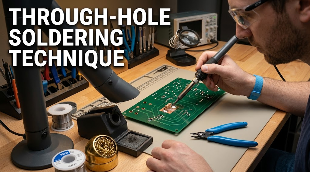
How to Solder Through-Hole Components Without Damaging a PCB?
The safest through-hole soldering technique supports the PCB, keeps the component still, heats the lead and pad together, feeds only enough solder to fill the plated hole and form the required fillet, then removes heat before moving the assembly. Use flux appropriate to the process, keep tip force light, and inspect the pad, barrel, solder side, and nearby vias. During removal, fully melt the joint before withdrawing the lead; never lever a partly molten connection.Commercial disclosure: QUICKO publishes this educational guide and sells soldering equipment and consumables. QUICKO links are commercial references. This tutorial does not promise a universal temperature, dwell time, tip life, power rating, or PCB-damage threshold for any specific QUICKO model.
Prepare the Board Before Heating
Start by identifying the component, pad, plated barrel, nearby vias, copper planes, and heat-sensitive parts. Confirm the board is de-energized and supported so it cannot flex when the iron or cutters touch it. Insert the component fully, orient it against the assembly drawing, and bend or retain the leads only enough to prevent movement. Excessive bending can stress the plated hole and make later removal harder.Clean visible contamination and select flux and solder compatible with the board finish and assembly process. Keep a stable rest for the soldering hand and a clear path for the iron. The QUICKO Products page can help identify current equipment categories, but the exact station, tip, solder, and flux manual controls model-specific settings and care.
Select the Right Tip and Heat Path
Choose a tip face that contacts the lead and the pad together without touching adjacent pads, mask, or plastic. A small conical face can reach a tight hole, while a chisel or bevel can transfer heat more efficiently to a larger annulus or ground-connected lead. The correct choice is the largest safe contact face, not necessarily the sharpest point.Keep the tip clean and lightly tinned according to the supplier’s care instructions. A dry or oxidized face may force longer dwell and more pressure. If the hole is connected to a large plane or thermal network, recognize that heat will leave the joint quickly. Improve coupling with a suitable geometry, approved preheat, or better workholding before simply increasing temperature.
Step-by-Step Through-Hole Soldering Technique
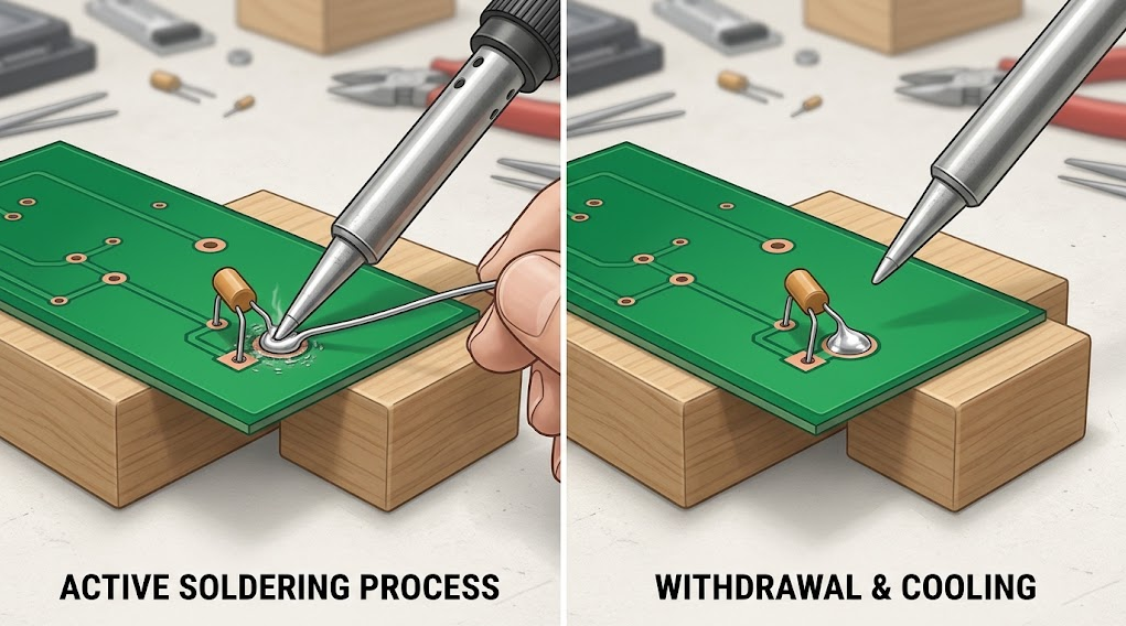
1. Stabilize the assembly. Rest the PCB and secure the component so neither moves during heating or solidification.2. Apply a small amount of flux. Use a compatible flux and avoid flooding nearby connectors or switches.
3. Heat pad and lead together. Touch the tinned tip to both surfaces at the joint, using light pressure.
4. Feed solder to the heated joint. Introduce solder at the pad–lead intersection, not onto an idle tip. Let it flow around the lead and into the plated barrel.
5. Stop at the required fill and fillet. Do not create a large blob that hides the hole, bridges neighbors, or traps residue.
6. Withdraw solder, then iron. Remove the solder first, then lift the iron smoothly while keeping the component still.
7. Allow solidification. Do not shake, bend, or trim the lead until the solder has solidified.
8. Inspect both sides. Check the solder-side fillet, lead position, pad edge, annulus, nearby vias, and component body.
The Adafruit soldering tutorial provides useful visual context for heating the joint and feeding solder to the heated surfaces. For production, pair this sequence with the workmanship standard specified for your product.
How Much Solder and Heat Is Enough?
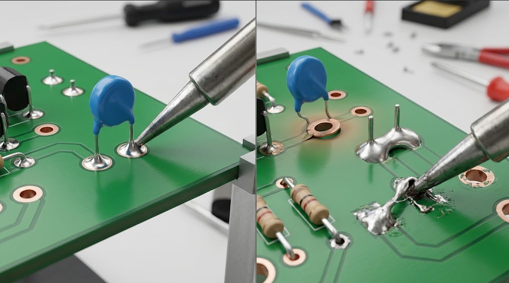
Use enough solder to create continuous wetting and the specified through-hole fillet, but not so much that the lead, hole, or neighboring pad disappears under a blob. The required volume depends on lead diameter, hole and pad geometry, board thickness, copper connection, solder alloy, and the applicable workmanship standard. A shiny surface alone does not prove barrel fill or mechanical integrity.Likewise, a higher setpoint is not a substitute for good coupling. Excess heat can lift pads, soften laminate, damage component seals, burn flux, and discolor the board. If the joint is slow, check tip wetting, contact area, flux activity, copper-plane heat sinking, and support. Change one variable at a time on a representative coupon and record the result.
Inspecting a Good Through-Hole Joint
| Inspection point | Acceptable observation | Warning sign | Response |
|---|---|---|---|
| Solder-side fillet | Continuous wetting and a controlled profile around the lead | Beading, gaps, cracks, or bridge | Rework under the approved method and inspect again |
| Lead position | Lead remains centered and component is seated | Tilted part, pulled lead, or movement | Stop and correct the mechanical setup |
| Pad and annulus | Pad edge and surrounding laminate remain intact | Lifted pad, torn annulus, blistering, or discoloration | Quarantine the board for repair review |
| Barrel and fill | Solder reaches the required depth or evidence defined by the standard | Incomplete fill or hidden void concern | Use the required inspection method; do not infer from top appearance |
| Nearby features | No bridge, solder ball, residue issue, or disturbed via | Bridge, spatter, or solder on a connector | Remove the defect and inspect adjacent conductors |
Formal workmanship documents may define acceptance differently for different classes of assembly. NASA workmanship guidance is a reference example, not a blanket requirement for every QUICKO reader or product.
Removing Through-Hole Components Safely
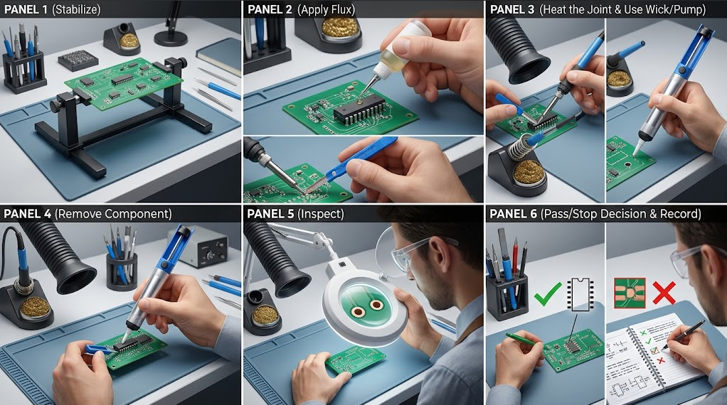
Removal creates more pad and barrel risk than initial assembly because the component lead may be mechanically locked by solid solder. First stabilize the board, add compatible flux, and fully melt the joint. Use solder wick, a desoldering pump, or a powered tool appropriate to the hole and board. Remove the component only when the lead can move freely; never twist or lever against the pad while solder is partly solid.After extracting the lead, clear the hole with the approved method and inspect the land, barrel, mask, and nearby vias. If the hole remains blocked, add a small amount of fresh solder or flux only when permitted by the process, then reheat with adequate contact. Do not keep heating a dry, unsupported pad. The iFixit soldering and desoldering guide provides general repair and safety context; your assembly documentation controls the repair limit.
Stop immediately for pad movement, laminate blistering, abnormal odor, delamination, damaged traces, or a lead that will not release without force. Record the condition before attempting a second method.
Three-Joint Validation Protocol
Before adopting a new through-hole tip, solder, flux, or station setting, run a repeatability check:9. Record station, handle, tip geometry, solder alloy, flux, board stack-up, component, hole geometry, and ambient conditions.
10. Inspect and photograph the cold tip and coupon if your quality system permits it.
11. Make three joints with the same operator sequence and workholding.
12. Record time to wet, dwell, solder amount, visible fillet, component movement, and any rework.
13. Inspect solder-side fillets, pad edges, annuli, barrels, mask, vias, and nearby conductors under magnification.
14. Perform continuity or mechanical checks required by the assembly’s acceptance standard.
15. Accept only when all three joints meet the same criteria; otherwise revise one variable and repeat.
This protocol produces configuration-specific evidence. It does not create a universal QUICKO temperature, recovery, or PCB-damage claim, and no first-party QUICKO results are supplied in this draft.
FAQ
Why does solder not fill the through-hole?
Check whether the lead and pad are hot together, whether the tip is clean and wetted, and whether a ground plane or thermal path is drawing heat away. Confirm the hole and lead geometry, flux activity, and solder feed. Improve coupling or use approved preheat before raising temperature. Inspect the solder side and use the required method to verify barrel fill.Is a conical tip best for every through-hole joint?
No. A conical tip can reach a restricted hole, but its small contact area may transfer heat slowly to a large pad or plane. A chisel or bevel can be more efficient when clearance allows. Choose the largest safe face that contacts the lead and pad together, then validate it on representative joints.How do I avoid lifting a pad during removal?
Support the board, add compatible flux, fully melt the solder, and remove the lead without levering. Use a suitable wick, pump, or powered desoldering tool and keep dwell controlled. If the lead resists, stop and reassess rather than pulling harder. Inspect the pad and barrel after removal before installing a replacement.Can I bend the leads to hold a component in place?
A small bend or approved retention method can prevent movement, but excessive bending stresses the plated hole and makes removal harder. Follow the assembly drawing and keep the lead aligned with the hole. The component should remain seated without forcing the pad or distorting the body.Does a shiny joint prove a good barrel connection?
No. Surface appearance does not prove complete barrel fill, hidden void absence, or mechanical strength. Inspect the visible fillet and use continuity, X-ray, cross-section, or other methods required by your product and workmanship standard. Document the method so another operator can reproduce the decision.What should I do if the PCB becomes discolored?
Stop heating and let the board cool. Record the location and inspect the laminate, pad, mask, nearby components, and traces for blistering, delamination, or movement. Do not continue until a qualified reviewer decides whether the board is repairable. Repeated discoloration usually signals a process or heat-coupling problem that needs correction.Where can I find QUICKO care information?
Start with the QUICKO FAQ and the exact station or tip manual. Product families can differ in geometry, controls, cleaning instructions, and supported consumables. Record the document revision and contact QUICKO support when a model-specific procedure is unclear; do not infer a setting from another station.Conclusion
To solder through-hole components without damaging a PCB, stabilize the board, select a suitable tip face, heat the lead and pad together, feed only enough solder to meet the required fillet, and keep the assembly still while it solidifies. During removal, fully melt the joint and never lever against a partly molten plated hole.Treat every new combination of station, tip, alloy, flux, component, and board as a configuration to validate. Three repeat joints, magnified inspection, electrical or mechanical checks, and clear stop conditions provide stronger evidence than a single attractive fillet. QUICKO-specific process claims should be added only after named technical review and first-party testing are available.


Linkedin:


