
 Tel:+86-13713635953
 Email:support@quicko.com.cn


How Do Cartridge Soldering Tips Heat Faster Than Traditional Tips?
How Do Cartridge Soldering Tips Heat Faster Than Traditional Tips?
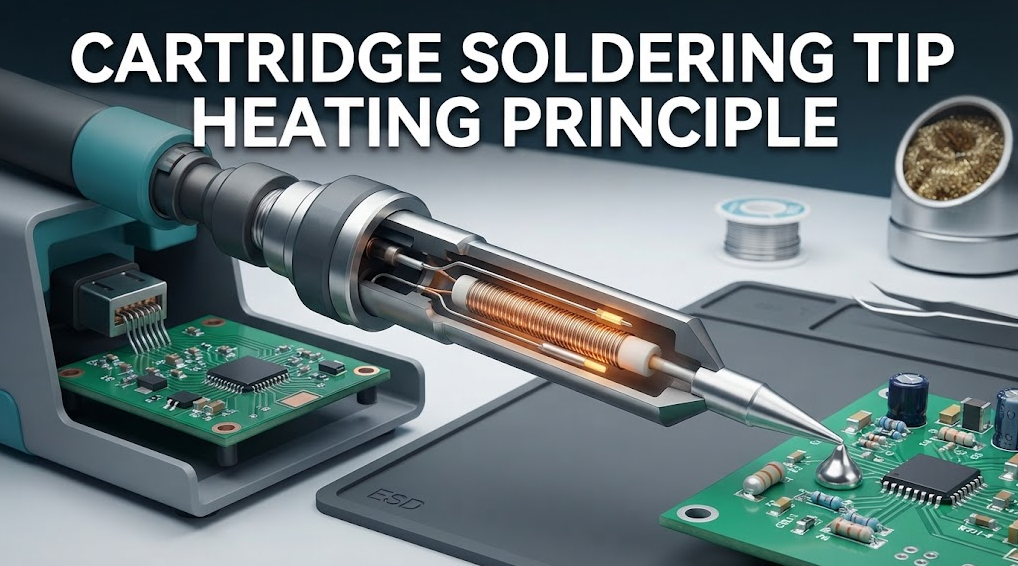
The cartridge soldering tip heating principle is mainly about shortening and stabilizing the heat path between the heater, temperature sensor, and working surface. In many cartridge designs, the heater and sensor are integrated close to the tip, so the controller can detect a load change with less thermal delay and replace heat nearer to the joint. That does not guarantee a faster result: tip mass, control tuning, power limits, contact area, and the test method still determine observed response.Commercial disclosure: QUICKO publishes this educational guide and sells soldering equipment and accessories. QUICKO links are commercial references. This article does not claim that any QUICKO cartridge has a particular internal layout, response time, heater rating, or certification without current documentation and configuration-specific testing.
Quick Navigation
- Understand the heater-to-joint path
- See why sensor placement changes apparent speed
- Compare cartridge and separated-heater architectures
- Separate heat-up speed from thermal recovery
- Check tip geometry, control, and power limits
- Measure response fairly
- Avoid common interpretation errors
What "Faster Heating" Actually Means
Heating speed can describe several different events. A station may reach a displayed setpoint quickly while the working surface is still below the useful process temperature. It may also recover quickly after a joint removes heat, which is a different test from cold start. Define the event before comparing products.| Term | What it should describe | Evidence needed |
|---|---|---|
| Cold-start heat-up | Time from a defined starting condition to a defined tip-temperature criterion | Starting temperature, setpoint, probe, tip, and criterion |
| Thermal recovery | Temperature and time response after a defined solder joint or load removes heat | Joint mass, dwell, solder, tip geometry, and logging method |
| Display response | Time for the controller display to show a target or stable reading | Sensor location, filtering, display update, and setpoint |
| Process readiness | Time until the real workpiece can be soldered consistently | Board, pad, solder, flux, operator method, and acceptance criteria |
These measurements should not be reported as interchangeable. A cartridge may look fast in cold-start testing but behave differently on a large copper plane. Conversely, a slower displayed ramp may still deliver a stable joint when the sensor and working surface are well matched.
The Cartridge Soldering Tip Heating Principle
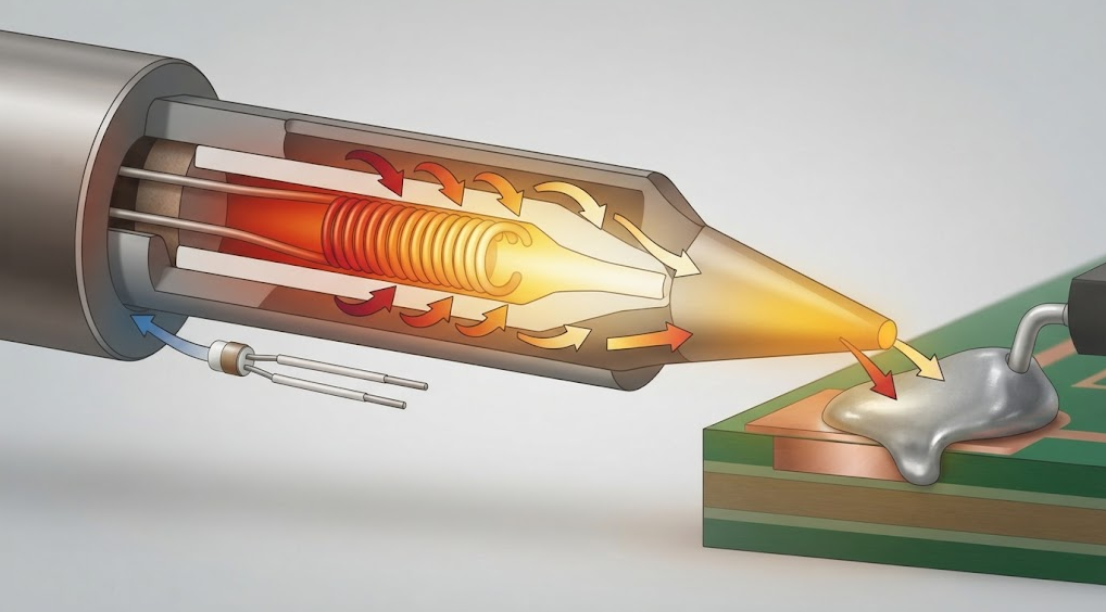
A simplified cartridge system has four thermal elements: heater, sensor, tip body, and joint. Electrical power becomes heat in the heater. Heat then travels through the metal structure to the working surface and into the soldered part. The sensor reports a temperature-related signal to the controller, which adjusts power according to its control method.The Microchip closed-loop control note explains why a shorter feedback path can make control more responsive, but it does not predict a result for a particular soldering tip. Real behavior still depends on resistance, supply, switching, firmware, sensor calibration, thermal contact, and the joint load.
Why Heater and Sensor Placement Matter
In a separated-heater design, the heater may sit farther from the working surface, with additional metal, mechanical interfaces, or air gaps between the heat source and the joint. Those elements can add thermal mass and resistance. They can also make the sensor's reading less representative of the actual contact point during a sudden load.In an integrated cartridge, the heater and sensor can be positioned closer to the tip. That arrangement may reduce the distance heat travels and reduce the volume that must change temperature before the controller sees a meaningful signal. The benefit is architectural, not automatic: a heavy tip, weak power stage, poor sensor calibration, or conservative control loop can still dominate behavior.
The Omega thermocouple resource is useful background on how sensor junctions produce a temperature-related signal and why wiring, reference conditions, and measurement setup matter. Do not infer the sensor type inside an unverified cartridge from the outside shape alone.
Thermal Mass, Tip Geometry, and Contact Area
The working tip must store and transfer enough heat for the joint. More metal can provide useful reserve, but it also takes more energy to change temperature. A small tip can respond quickly in free air while losing temperature rapidly when it touches a large copper area. A larger bevel or knife may transfer heat effectively because it increases contact area, even if its displayed temperature changes more slowly.Compare the shape, mass, plating, reach, and contact area together. The Hakko tip-selection guidance illustrates why tip geometry is an application choice rather than a simple size ranking. It is not evidence that another brand's cartridge has the same construction or result.
Cartridge Versus Traditional Separated-Heater Architecture
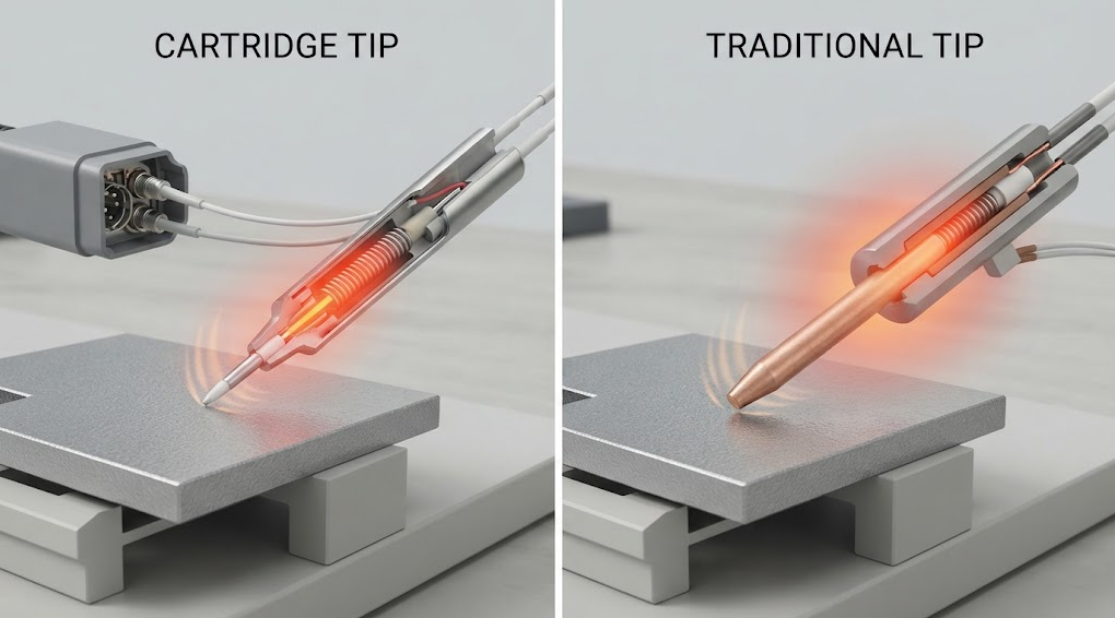
| Design question | Integrated cartridge | Separated-heater tip and handle |
|---|---|---|
| Heat path | Heater and sensor are generally closer to the working surface | Heat crosses more mechanical structure before reaching the tip |
| Sensor relationship | Potentially closer to the point of contact | May be farther from the working surface or affected by interfaces |
| Tip change | Cartridge or integrated tip may be replaced as one unit | Tip and heater may be serviced as separate parts, depending on design |
| Service trade-off | Faster swaps can simplify handling but may raise consumable cost | Separate parts can offer flexibility but require compatibility checks |
| What still needs testing | Control tuning, mass, power, calibration, connector, and joint load | The same factors, plus heater-to-tip interfaces and sensor distance |
This table describes architecture tendencies, not a promise for every product sold under either category. Manufacturer revision, controller, tip geometry, and maintenance condition can outweigh the broad design label.
Control Loop, Power, and Connector Limits
A responsive cartridge still needs a controller that can measure and command it predictably. Check the sensor signal, sampling interval, filtering, control method, heater resistance, supply limits, switching device, connector contacts, and safe-off behavior. A controller can only replace heat as quickly as the power stage and heater allow, and it can only regulate what the sensor represents.Define fault responses for an open sensor, shorted or implausible reading, disconnected cartridge, brownout, watchdog event, and over-temperature condition. A display warning is not the same as a safe-off mechanism. For any QUICKO model, use the QUICKO Products page to identify the current product category, then request the exact manual and compatibility record before assuming a cartridge architecture or controller behavior.
How to Measure Heating and Recovery Fairly
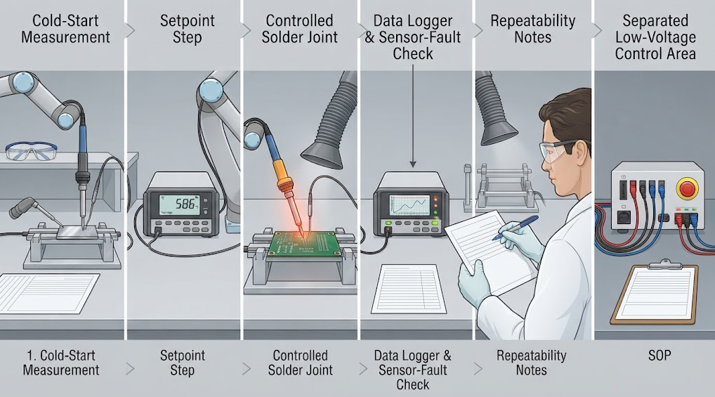
- Freeze the tip, handle, station, firmware or controller revision, supply, solder, flux, test coupon, and instrument.
- Record the starting temperature and ambient conditions. State whether the tip was freshly tinned, cleaned, or preheated.
- Define the endpoint: displayed setpoint, measured working-surface temperature, process-readiness criterion, or a combination.
- For recovery, use the same joint geometry, copper mass, dwell time, solder, flux, and contact pressure for every candidate.
- Log the measured tip or joint temperature with a stated sensor method and sampling interval. Do not substitute the display value silently.
- Repeat cold-start and recovery measurements enough to expose variation, then report the range or distribution rather than one attractive run.
- Inspect the joint, nearby materials, tip wetting, and operator method. A quick temperature trace that produces poor joints is not a successful process.
Common Mistakes When Interpreting Cartridge Speed
Comparing different tip sizes
A small tip and a large bevel do not present the same thermal load. Keep geometry and contact area controlled or describe the difference clearly.Treating display time as working-surface time
The controller display may reflect a filtered sensor near the heater, not the exact metal surface touching the joint.Testing in air only
Free-air heating hides the heat drawn by copper, shields, connectors, ground planes, and other real workpieces.Ignoring calibration and sensor condition
Sensor offset, connector resistance, oxidation, plating wear, and calibration can change both the reading and the control response.Repeating an unverified competitor number
A published response figure is meaningful only with its starting state, tip, load, instrument, endpoint, and revision. Treat it as contextual until reproduced.Selection Checklist
- [ ] Heater, sensor, tip body, and connector architecture are documented for the exact cartridge.
- [ ] “Faster” is defined as cold-start, recovery, display response, or process readiness.
- [ ] Tip geometry, mass, plating, reach, and contact area match the intended joint.
- [ ] Controller sampling, filtering, control method, power stage, and safe-off behavior are understood.
- [ ] Starting temperature, setpoint, load, probe, endpoint, and sampling interval are recorded.
- [ ] Tests include a real copper or board load, not free-air heating only.
- [ ] At least three representative joints are inspected for wetting, dwell, rework, and nearby-material condition.
- [ ] Results are repeated after cartridge, tip, controller, firmware, or calibration revisions.
- [ ] A named technical reviewer has checked the thermal and electrical assumptions.
FAQ
Do cartridge soldering tips always heat faster?
No. Integration can shorten the heater-sensor path, but observed speed also depends on tip mass, contact area, controller tuning, power limits, calibration, and the test load. Compare the same tip geometry, starting condition, endpoint, instrument, and joint before concluding that one architecture is faster.What is the main advantage of putting the heater inside the cartridge?
The main potential advantage is a shorter thermal path between the heater, sensor, and working surface. That can reduce delay when the joint removes heat. It does not eliminate the need for correct control, adequate power, sound connections, calibration, and a tip geometry matched to the workpiece.Is a cartridge tip better for precision electronics?
It can be useful when the cartridge geometry, sensor behavior, and handle access fit small pads and dense boards. “Better” still depends on tip reach, contact area, solder, flux, operator technique, and the board. Qualify the actual cartridge and process instead of inferring performance from the word cartridge.Why can a tip heat quickly in air but cool on a PCB?
Copper, planes, connectors, shields, and large leads draw heat from the tip. Air testing has little thermal load, so it can overstate process performance. Recovery testing should use a defined coupon or representative joint and record the same contact, dwell, solder, and tip conditions.Can I compare response-time numbers from different brands?
Only when the methods are comparable. Check the tip, start temperature, setpoint, load, probe, endpoint, sampling rate, software filtering, and revision. If any of these differ, label the comparison as contextual rather than treating the numbers as a controlled benchmark.Does a closer sensor remove the need for calibration?
No. Sensor proximity can improve the relationship between measured and working-surface temperature, but offset, wiring, reference, aging, connector condition, and controller calibration still matter. A cartridge should be tested and maintained as part of the complete station configuration.Conclusion
The cartridge soldering tip heating principle is a shorter, more integrated heater-to-sensor-to-tip path, but “faster” is meaningful only when the starting state, tip geometry, thermal load, endpoint, and measurement method are controlled. Use the architecture to form a hypothesis, then verify cold-start behavior, loaded recovery, control faults, joint quality, and repeatability on the exact station and cartridge.QUICKO product and News pages can help organize related equipment and tip research, while model-specific layout, temperature, power, response, and compatibility claims require current documentation, qualified review, and configuration-specific tests.


Linkedin:


