
 Tel:+86-13713635953
 Email:support@quicko.com.cn


Soldering Iron Troubleshooting: Symptoms, Causes, and Fixes
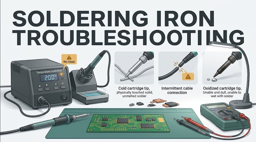
Soldering Iron Troubleshooting: Symptoms, Causes, and Fixes
Soldering iron troubleshooting should begin with the symptom, not with random part swapping. Disconnect the tool, let it cool safely, record what happened, inspect the tip-to-supply path, and change one known-compatible variable at a time. A cold tip may come from the cartridge, handle, cable, connector, controller, power supply, or protection logic; poor soldering can also come from oxidation, unsuitable tip geometry, contaminated surfaces, or a large thermal load even when the display looks normal.This guide helps technicians and electronics users separate simple maintenance problems from faults that require qualified service. It covers temperature-controlled stations, cartridge systems, compact portable tools, and conventional irons at a general level. The exact product manual, wiring diagram, approved test procedure, safety data, and workplace rules take precedence.
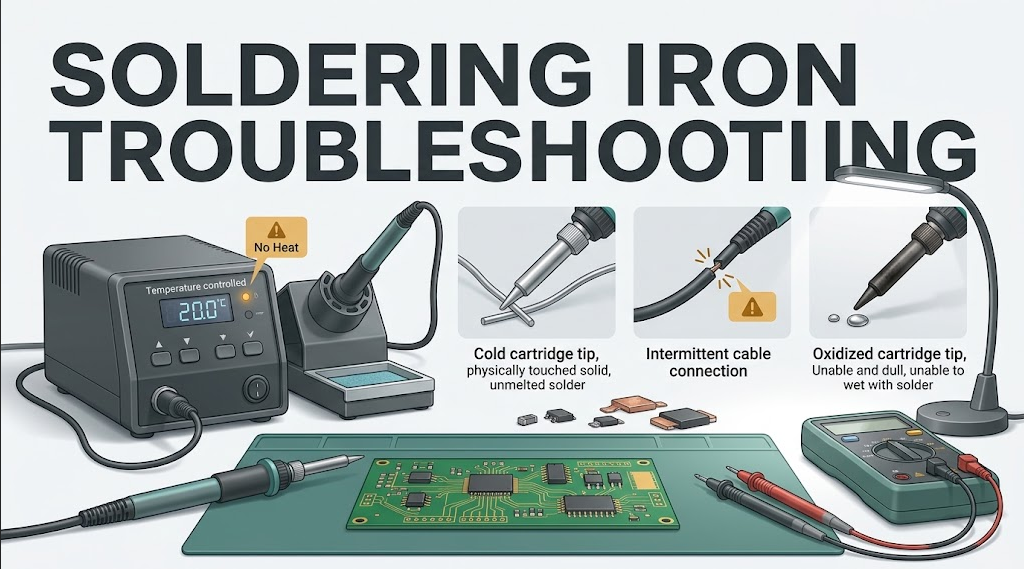
Quick Answer: Why Is My Soldering Iron Not Working?
A soldering iron may fail because power is absent, the supply enters protection, the heater or sensor circuit is open, a cartridge is incompatible or poorly seated, the handle cable is intermittent, the controller has detected a fault, or the tip cannot transfer heat into the joint. Start with the manual, power removed, and a visual inspection. Then test one approved known-good part at a time. Stop immediately for smoke, odor, arcing, exposed conductors, tingling, uncontrolled heat, repeated fuse operation, or enclosure damage.What r/soldering Troubleshooting Posts Repeatedly Show
Across relevant `r/soldering` posts and comments, users often call a heat-transfer problem an iron failure. The recurring first checks are whether the working face is clean and tinned, whether the tip geometry provides enough contact area, whether flux and a small molten solder bridge are present, and whether the joint has unusually high thermal mass. These observations are useful diagnostic clues, but the station manual and product-specific limits still control.Three discussion patterns are especially useful:
- In a new station that would not heat properly, the reported cause was a 220 V versus 127 V supply mismatch. The lesson is to verify the nameplate and regional input before assuming a heater failure. Never touch the metal parts to judge temperature.
- In a discussion about a joint that would not melt, repeated suggestions included tinning the tip, adding compatible flux and fresh solder, increasing contact area, and changing from a very narrow tip to a broader geometry. Several comments also recommended simply raising the setpoint; that is not a universal fix and can damage the work.
- In a new cartridge reporting “tip damaged”, other cartridges worked normally. The useful diagnostic pattern is compare installation and compatibility, then substitute one known-good cartridge. Resistance numbers posted by users are model-specific anecdotes, not generic pass/fail limits.
Table of Contents
- Safety limits and stop conditions
- Diagnostic order and required tools
- Symptom-to-cause troubleshooting table
- No power or no heat
- Slow heating and weak joints
- Temperature fluctuation and error codes
- Tip wetting and oxidation problems
- Cartridge, handle, cable, and connector checks
- Controller and power-supply boundaries
- Repair-or-replace decisions
- Preventive maintenance
- Frequently asked questions
Safety Limits: When Should You Stop Troubleshooting?
Unplug the station before opening, cleaning, reseating, or measuring anything unless the manufacturer provides a specific qualified-service procedure. A switch in the off position is not the same as physical isolation. Let the cartridge cool in its stand, remove batteries where the design permits, and allow stored energy to discharge according to the manual.Stop and quarantine the tool when any of these conditions appears:
- Smoke, unusual odor, scorching, melted insulation, arcing, or a glowing heater or tip
- Tingling, shock, unexpected voltage on exposed metal, damaged protective earth, or a failed insulation test
- A cracked enclosure, exposed conductor, crushed cable, loose mains inlet, wet contamination, or liquid entry
- Repeated fuse or breaker operation, a replacement fuse that opens again, or a supply that cycles rapidly
- Uncontrolled heating, extreme overshoot, or a temperature display that cannot be trusted
- A swollen, damaged, leaking, or abnormally hot battery in a portable tool
- Missing documentation for a modified controller, unknown wiring, or an unverified cartridge adapter
Use a Fixed Diagnostic Order
Troubleshooting becomes faster when every case follows the same path:- Capture the symptom. Record the model, controller message, setpoint, cartridge part number, supply, time to failure, recent changes, and whether the problem is constant or intermittent.
- Make the system safe. Power down, unplug, place the handpiece in the stand, and let it cool. Isolate batteries or external supplies as documented.
- Inspect without disassembly. Check the tip, cartridge seating, handle sleeve, strain relief, cable, plug, connector pins, stand, supply cable, and enclosure.
- Return to a known configuration. Remove unverified adapters, restore documented settings, and use only the specified handle, cartridge, supply, and firmware profile.
- Change one variable. Where the manual permits, substitute one known-good compatible cartridge, handle, or external low-voltage supply. Do not swap several parts together.
- Verify under a defined load. A display at idle is not proof of joint performance. Test a representative copper load with a clean, tinned, suitable tip and record the result.
- Escalate or quarantine. If the fault remains, protect the evidence and refer the tool for qualified service rather than bypassing protection.
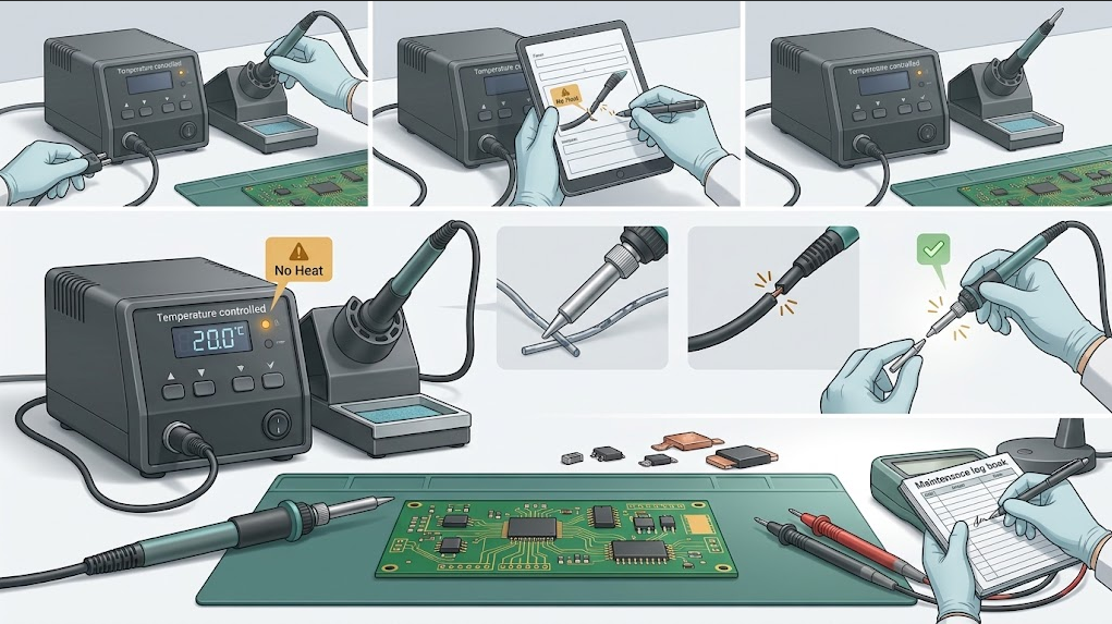
Soldering Iron Troubleshooting Table
| Symptom | Likely areas | Safe first checks | Stop or escalate when |
|---|---|---|---|
| No display or power indication | Outlet, external supply, cable, switch, inlet, fuse, controller | Confirm the documented source and connections; inspect damage while unplugged | Fuse repeats, enclosure is damaged, or mains service is required |
| Display works but tip stays cold | Cartridge heater, contacts, handle cable, power stage, protection logic | Reseat one cool approved cartridge; inspect contacts; try one known-good compatible cartridge | The station reports uncontrolled heat, odor, arcing, or repeated protection |
| Heats slowly | Low supply capacity, current limiting, high contact resistance, worn heater, wrong cartridge | Verify the specified supply and configuration; inspect cool connectors and strain relief | Connector heats, insulation discolors, or the supply cycles |
| Display is stable but joints remain cold | Narrow or oxidized tip, poor wetting, large copper mass, weak thermal bridge | Clean and tin the tip; choose a broader safe face; add compatible flux; test a defined load | Board damage or excessive dwell begins |
| Temperature jumps or flickers | Intermittent cable, dirty contacts, sensor fault, wrong profile, noise | Inspect and gently position the cool cable; restore documented settings; substitute one approved part | Heat becomes uncontrolled or movement exposes conductors |
| Overshoot or continuous heating | Sensor path, wrong sensor type, controller profile, failed power switch | Switch off immediately; verify documented cartridge/controller pairing | Always: do not keep operating an uncontrolled heater |
| Error code | Sensor/heater detection, cartridge absence, stand mode, supply protection | Record the exact code and consult the exact manual | Code relates to safety, isolation, overtemperature, or internal power fault |
| Solder will not wet the tip | Oxidation, contamination, damaged plating, incompatible materials, insufficient heat | Use maker-approved cleaning, compatible flux, and fresh solder | Plating is cracked, pitted, distorted, or exposes core metal |
| Station resets during contact | Supply voltage collapse, current limit, connector resistance, cable fault | Check the documented supply and connectors; compare idle versus defined-load behavior | Battery/supply heats abnormally or protection repeats |
| Tingling or unexpected voltage | Grounding, insulation, leakage, wiring modification | Disconnect and quarantine | Always: qualified safety testing is required |
No Power: Start Outside the Enclosure
If the display and heater are both dead, begin with the parts that can be checked without opening a mains-powered enclosure. Confirm that the correct outlet, detachable lead, adapter, battery, or external DC supply is being used. Read the station and supply nameplates instead of relying on the seller listing or memory. A Reddit voltage-mismatch case was resolved only after the owner noticed that a 220 V station had been connected to a 127 V source. Check whether the supply has its own indicator or protection state. Inspect plugs, sockets, strain relief, and cables for cuts, crushing, heat damage, looseness, or contamination.Never touch a tip, cartridge, heater barrel, or other metal part to decide whether the iron is hot. Use the station's documented indication or a suitable temperature-verification method, keep the handpiece in its stand, and treat the assembly as hot until it has cooled.
Do not assume a larger fuse is a repair. A fuse is a protective device, and replacing it with a higher rating, foil, wire, or a bypass can turn an existing fault into a fire or shock hazard. If the exact approved replacement opens again, stop. The underlying fault must be found by qualified service.
For a low-voltage external supply, verify only the output type, polarity, connector, voltage, and current capability specified by the station manual. A supply label that looks close is not enough. USB-C tools may also require a negotiated Power Delivery profile; a cable or source can power the display while failing when heater power is requested.
Display Works but the Soldering Iron Does Not Heat
This symptom narrows the problem to the heater path, cartridge contacts, handle cable, power stage, or protection logic. With the system unplugged and cool, remove and reinstall the approved cartridge exactly as the manual describes. Inspect for bent contacts, debris, discoloration, plating loss, an incompletely seated tip, or a loose retaining mechanism.If the manufacturer permits substitution, try one known-good cartridge from the exact supported family. A successful substitution points toward the original cartridge; it does not prove that every other component is healthy. If the replacement also stays cold, the handle, cable, connector, supply, or controller becomes more likely.
Cartridge families are not interchangeable simply because they look similar. QUICKO's T12 soldering tip range and its C210/C245 cordless station listing illustrate different system contexts. Confirm the exact cartridge, handle, controller profile, connector, power source, and grounding path as one system before energizing it.
Resistance or continuity measurements can help only when the exact service manual identifies the correct isolated contacts, expected conditions, and acceptable range. Do not invent pinouts from online photographs, and never use resistance mode on an energized circuit. Some cartridge systems share heater and sensor conductors or require a specific measurement method.
Why Does the Iron Heat Slowly or Feel Weak?
A station can reach the displayed setpoint at idle and still fail at the joint. The sensor may be closer to the heater than the working face, while a narrow tip, dry contact, oxidized surface, loose interface, undersized supply, large ground plane, connector, shield, or chassis pulls heat away faster than the system can deliver it.Check the heat-transfer path before raising the temperature:
- Use the largest safe working face that can contact the pad and lead together.
- Clean and tin the tip so a small solder film forms a thermal bridge.
- Apply compatible electronics flux to improve wetting.
- Stabilize the work so the joint does not move during contact.
- Verify that the supply, handle, cartridge, and controller are the documented combination.
- Compare performance on a small reference joint and a representative high-mass load.
That same distinction appears clearly in the `r/soldering` thread “Impossible to melt this joint”. The successful report combined fresh solder, flux, a tinned working face, steadier contact, and a plan to use a more suitable geometry. Treat that as a diagnostic pattern, not a recipe for a particular temperature: the safe setting depends on the alloy, flux, component, board, tip, station, dwell time, and manufacturer guidance.
Do not solve every weak joint with a higher setpoint. Excess temperature can accelerate oxidation and damage pads, components, insulation, or laminate while leaving poor contact unchanged.
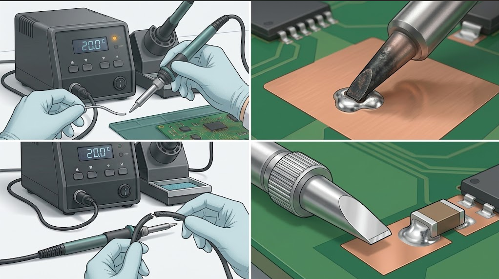
Temperature Flicker, Overshoot, and Error Codes
An unstable display can come from a sensor contact, intermittent cable, wrong cartridge profile, connector contamination, electrical noise, unstable reference, supply problem, or controller fault. Record whether the value changes when the cool cable or handle is repositioned, when the station wakes from sleep, or when the tip touches a defined load. Never flex a damaged cable while the tool is hot or energized.Large overshoot, a glowing tip, or continuous heating is different from ordinary display variation. Switch off and unplug immediately. Feedback may be missing or the power switch may have failed. Continuing to run the tool “to see what happens” risks destroying the cartridge, board, handle, and safety insulation.
Copy the exact error code, model, firmware version if shown, cartridge part number, and operating state. A generic internet explanation is not a substitute for the correct manual. JBC's manufacturer description of its integrated heating, sleep, and hibernation system shows why the controller, heater, sensor, stand detection, and cartridge operate as a system; other brands and third-party implementations may use different fault logic.
When one cartridge triggers an error but other approved cartridges work, first verify seating, cleanliness, exact family compatibility, and the station profile, then repeat the comparison once with a known-good part. The `r/soldering` “tip damaged” discussion illustrates this one-variable method. Do not copy the resistance values from that thread into a different cartridge system; use only the contacts, conditions, and tolerances specified for the exact model.
Why Will Solder Not Stick to the Tip?
When solder beads up and rolls away, the working face may be oxidized, contaminated, damaged, below the process temperature, or incompatible with the solder and flux. Start with the cleaning and recovery method approved for the exact plated tip.- Put the handpiece in a safe stand and use eye protection.
- While the tip is at the approved working condition, clean it lightly with brass wool, a damp sponge, or the maker-approved method.
- Apply compatible electronics-grade flux or tip cleaner only as directed.
- Feed fresh solder across the working face until a thin, even coating forms.
- Wipe lightly and re-tin immediately.
- If the face remains black, repels solder, or shows holes, cracks, exposed core, distortion, or severe erosion, replace it.
QUICKO lists black-finish T12 tip options, but a finish name or dark appearance is not itself a fault diagnosis. Judge the actual working face by documented coating, wetting, geometry, surface damage, and compatibility.
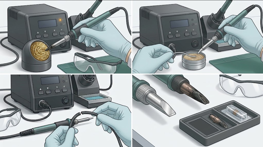
Inspect the Cartridge, Handle, Cable, and Connector
Intermittent faults often appear at moving or high-cycle interfaces. With power removed and the assembly cool, inspect:- Cartridge contacts for debris, discoloration, pitting, looseness, or incomplete seating
- Handle threads, sleeves, retainers, and insulating parts for cracking or heat damage
- Cable entry and strain relief for kinks, crushing, cuts, stiffness, or separation
- Connector pins and shells for bending, push-back, contamination, or looseness
- Stand sensor, motion sensor, magnetic trigger, or sleep switch for alignment and damage
- Grounding contacts specified by the manufacturer
If a cable fault changes with movement, stop using the tool. Repeated flexing can turn a partial conductor break into arcing or expose a live conductor. Replace the handle or cable assembly with the approved part, or refer it for documented repair.
Controller and Power-Supply Boundaries
Once a known-good compatible cartridge and handle have been checked, the remaining path includes the external supply, station input, protection devices, power switch, sensing circuit, controller, firmware, and grounding system. These areas may expose hazardous energy even after unplugging.A qualified technician can use the service documentation to verify isolated low-voltage rails, heater drive, sensor response, connector continuity, grounding, insulation, and protection behavior. The correct limits depend on the exact model. This guide intentionally does not provide a generic live-probing sequence because copying one circuit's test points to another controller can damage the equipment or the person testing it.
For portable systems, stop using a battery that swells, leaks, smells unusual, is mechanically damaged, or becomes abnormally hot. Use only the approved charger and power path. For USB-C systems, confirm the required protocol and cable rating rather than assuming every USB-C source supplies the same power.
Repair, Replace, or Send for Service?
Use three questions to decide:Is the fault isolated to a consumable?
A worn, oxidized, cracked, or electrically open approved cartridge is usually replaced rather than rebuilt. Record the failure and inspect why it occurred: excessive idle temperature, lack of tinning, aggressive cleaning, mechanical damage, contamination, or an incompatible controller can damage the replacement too.Is a modular part documented and available?
An approved handle, cable, stand sensor, connector assembly, external supply, or controller module may be replaceable without component-level repair. Confirm part numbers and perform the manufacturer's post-replacement checks. Mechanical fit alone is insufficient.Does the repair affect electrical safety or calibration?
Mains wiring, insulation, protective earth, leakage barriers, power switching, batteries, and uncontrolled-heating faults require qualified service and appropriate post-repair tests. If the equipment cannot be returned to its documented safety and calibration state, replace or quarantine it.For a B2B fleet, compare downtime, labor, test-equipment needs, spare availability, warranty, traceability, and the consequence of recurrence. A low-cost board repair is not economical if it cannot be verified safely or consistently.
Preventive Soldering Iron Maintenance
Maintenance reduces both failures and diagnostic ambiguity:- Inspect the tip, handle, cable, connector, stand, and supply before each shift or critical job.
- Keep the working face tinned before use, during pauses, and at shutdown according to the tip maker's procedure.
- Use sleep or standby rather than leaving the tip at full working temperature during idle periods.
- Clean only with approved materials; keep abrasive tools away from plated working faces.
- Record cartridge changes, fault codes, calibration checks, cable repairs, and recurring resets.
- Keep one known-good compatible cartridge and, where justified, one verified handle or supply for controlled substitution.
- Quarantine failed parts so they are not returned to service accidentally.
- Review recurring failures by station, operator, alloy, flux, setpoint, joint type, and shift before blaming a single component.
Frequently Asked Questions
Why is my soldering iron on but not heating?
The display and control electronics may have power while the heater path is open or disabled. With the station unplugged and cool, verify the approved cartridge is fully seated, inspect contacts and the handle cable, and try one known-good compatible cartridge if the manual permits. Stop for odor, arcing, repeated protection, or uncontrolled heat.Why does my soldering iron melt solder but not heat the joint?
The tip may be too narrow, oxidized, dry, poorly positioned, or unable to recover against the joint's copper mass. Use a clean tinned face that contacts both surfaces, add compatible flux, and select the largest safe geometry. Verify the supply and cartridge system before increasing the temperature.Can I test a soldering iron heater with a multimeter?
Only when power is removed and the exact service documentation identifies the isolated contacts, test method, and acceptable range. Cartridge pinouts and combined heater/sensor arrangements vary. Never use resistance mode on an energized circuit, guess from connector appearance, or probe inside a mains-powered station without the required qualification and safety equipment.Should I replace a tip that will not take solder?
First use the manufacturer-approved light cleaning, flux or tip-recovery compound, and fresh solder. Replace the tip if the working face still repels solder or shows cracks, holes, exposed core metal, distortion, or severe erosion. Do not file a plated tip to create a temporary wettable surface.Why does my soldering station reset when I touch a large joint?
The heater demand may expose a weak or undersized supply, current limit, voltage drop, high-resistance connector, intermittent cable, or protection event. Record idle and loaded behavior using the documented supply. Stop if the supply, battery, cable, or connector heats abnormally or if protection repeats.Is it safe to repair a soldering station myself?
Tip care and approved modular replacement may be suitable for trained users with power removed. Mains wiring, insulation, protective earth, leakage, battery damage, power-stage faults, and uncontrolled heating require qualified service and post-repair safety tests. When documentation or test equipment is missing, quarantine or replace the station.Conclusion
Reliable soldering iron troubleshooting follows the energy path from source to supply, controller, connector, handle, heater, tip, and joint. It also checks the feedback path from sensor to controller and the practical heat-transfer path from a clean tinned face into the work. A stable display alone cannot prove that every link is healthy.Begin with power removed, capture the exact symptom, restore a documented configuration, inspect visible interfaces, and substitute only one known-compatible part at a time. Fix contact, wetting, geometry, and load problems before raising temperature. Stop immediately for electrical-safety symptoms, uncontrolled heat, repeated protection, battery damage, or faults that require opening energized equipment.
To plan a QUICKO service bench, match replacement tips, handles, controllers, supplies, stands, and test procedures to the exact station family. Keep known-good diagnostic parts traceable, record failures, and verify repaired equipment before it returns to production.


Linkedin:


