
 Tel:+86-13713635953
 Email:support@quicko.com.cn


How to Compare T12, C210, and C245 Soldering Systems?
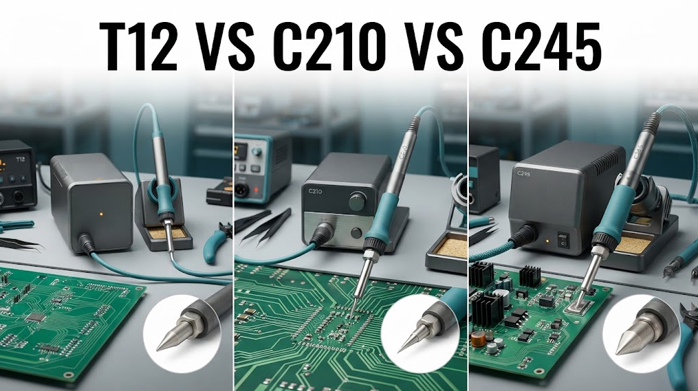
How to Compare T12, C210, and C245 Soldering Systems?
When comparing T12 vs C210 vs C245, start with the workpiece and joint, then check tip access, thermal mass, sensor behavior, handle ergonomics, power-stage requirements, service parts, and qualification evidence. T12 is often chosen for a broad general-purpose ecosystem, C210 for compact precision work, and C245 for larger heat-demanding joints, but those are starting hypotheses, not universal specifications. Confirm the exact manufacturer configuration before an OEM purchase.Commercial disclosure: QUICKO publishes this educational guide and sells soldering equipment and accessories. QUICKO links are commercial references. This article does not claim that any QUICKO station uses a particular T12, C210, or C245 implementation, nor does it guarantee a result for a customer's process.
Quick Navigation
- Define the workload before choosing a family
- Compare the three system families by decision criteria
- Match tips and thermal mass to the joint
- Check controls, power, and safety evidence
- Evaluate ergonomics and serviceability
- Build a procurement scorecard
- Qualify the final configuration
Define the Workload Before Comparing Families
The right soldering system depends on the joint, not the label. Record the smallest pad or lead you must access, the largest thermal mass you must heat, the board material, the solder and flux, the allowable dwell time, the duty cycle, and the operator's posture. A repair bench, a phone-rework cell, and an OEM production line can reasonably choose different systems even when they work on the same broad product category.Capture five workload signals:
- Geometry: fine-pitch pins, small SMD pads, through-hole leads, shields, connectors, or ground planes.
- Thermal demand: copper area, plane connection, joint mass, preheating, and how quickly the joint pulls heat away.
- Access: tip clearance, nearby plastics, shields, tall components, and whether the operator needs a short or angled handle.
- Repeatability: one-off repair, technician-to-technician variation, or a documented production recipe.
- Service model: local tip stock, cartridge replacement, calibration records, training, and spare-handle availability.
T12 vs C210 vs C245: What to Compare
The family names are useful shorthand, not a complete specification. Use the table as a screening framework and replace every generic cell with the exact supplier documentation.| Decision criterion | T12 family | C210 family | C245 family |
|---|---|---|---|
| Typical selection logic | Broad general-purpose tip and handle options are often attractive for mixed bench work | Compact geometry is often attractive where access and precision dominate | Larger cartridge or tip options are often attractive where the joint demands more heat transfer |
| Best starting workload | General PCB repair, through-hole work, and mixed tasks when tip access is adequate | Fine pads, small leads, dense boards, and short controlled touches | Larger connectors, shields, planes, and joints with higher thermal mass |
| Main question | Does the available tip geometry cover both the smallest and most common joints? | Can the small tip reach the joint while maintaining enough heat transfer? | Is the added size and heat capacity justified by the joint and operator workflow? |
| Risk of a poor match | Too much tip for a dense board or too little reserve for a large joint | Tip overload, long dwell, or limited reach on heavy copper | Excessive tip size, collateral heating, or reduced access around small components |
| Evidence to request | Exact handle, connector, sensor, tip list, control range, and power-stage limits | Exact fine-tip geometry, cartridge data, replacement policy, and measured process window | Exact high-mass tip geometry, power requirements, thermal test method, and service parts |
These are application hypotheses, not promises. A manufacturer's cartridge construction can change the result, and a well-designed control system can make two families feel closer or farther apart than their names suggest.
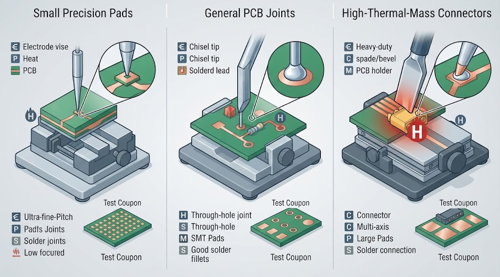
Match Tip Geometry and Thermal Mass to the Joint
Tip size is a heat-transfer decision. A tip that is too small may lose heat faster than the station can replace it; a tip that is too large may touch adjacent pads, obscure the joint, or transfer heat where it is not wanted. Compare contact area, reach, bevel or knife geometry, plating condition, and the distance between the heater or sensor and the working surface.For a high-mass joint, do not jump straight to the family with the largest headline power. First verify the actual tip contact area, heater-to-tip path, setpoint stability, board preheat, and allowable dwell. For a precision joint, do not assume a fine tip is automatically safer; check whether the tip can deliver heat without requiring excessive dwell or repeated rework.
The Microchip closed-loop control note explains why feedback and tuning affect a thermal system, but its equations and examples are not a qualification result for a specific soldering family. Measure the final handle, cartridge, controller, supply, and tip as one configuration.
Compare Controls, Power, and Safety Evidence
Two stations can accept the same family name while differing in sensing, control, display behavior, calibration, fault handling, and power architecture. Ask suppliers for the control method, sensor type, connector pinout, compatible handles, operating limits, and fault response. Require evidence for the actual configuration rather than relying on a web listing.Use these pass/fail gates:
| Gate | Pass evidence | Red flag |
|---|---|---|
| Compatibility | Written match between station, handle, cartridge or tip, and connector revision | "Universal" wording without a pinout or manual |
| Thermal behavior | Test method, instrument details, workload, and repeatable observations | A single recovery number without conditions |
| Control and calibration | Setpoint behavior, sensor assumptions, calibration procedure, and revision record | Temperature claims with no sensor or calibration context |
| Fault response | Sensor disconnect, out-of-range, brownout, and safe-off behavior are documented | UI alarm is the only stated protection |
| Electrical boundary | Supply, isolation, grounding, enclosure, and qualified review are clear | Exposed conductors or undocumented modifications |
| Service lifecycle | Tip stock, spare handles, replacement policy, firmware or controller support | A low purchase price with no parts or service path |
The OSHA electrical safety guidance is a general safety reference, not an approval for any station. OEM teams should apply their own risk assessment and applicable standards.
Evaluate Ergonomics and Serviceability
The operator experiences the handle, cable, balance, grip temperature, tip-change method, visibility, and fixture access - not the family name. Observe the system during the longest realistic task, not only during a five-minute demonstration. Record wrist angle, cable drag, tip-change interruptions, fume position, and whether the display or controls can be used without leaving the joint.Serviceability is equally practical. Compare local tip availability, tip identification, storage, cleaning, cartridge replacement, spare-handle lead time, calibration ownership, and training material. A system that performs well but is frequently unavailable can create more process risk than a slightly less capable system with reliable parts.
For QUICKO equipment categories and current model documentation, start with the QUICKO Products page and request the exact manual or compatibility record before treating a family-level comparison as a product recommendation.

Build a Procurement Scorecard
Use weighted scores only after you define pass/fail gates. A simple example is below; change the weights to match the job and record the evidence source for every score.| Category | Suggested question | Evidence owner |
|---|---|---|
| Joint coverage | Does the system cover the smallest and largest required joints without forced workarounds? | Process engineer |
| Thermal control | Does the configuration hold the process window under the defined load? | Test engineer |
| Access and ergonomics | Can operators reach the joint and work for the full task without avoidable strain? | Production or repair lead |
| Repeatability | Can different operators reproduce the approved joint recipe? | Quality lead |
| Service | Are tips, handles, calibration, and repair support available for the planned life? | Procurement and service |
| Traceability | Can the team record station, handle, tip, firmware, calibration, and revision? | Quality system owner |
| Total cost | Do purchase, consumables, downtime, training, and spares fit the lifecycle budget? | Procurement |
Do not average away a safety or compatibility failure. A station that fails a mandatory gate should be rejected or quarantined even if its weighted score is high.
Qualify the Final T12, C210, or C245 Configuration
- Freeze the exact station, handle, cartridge or tip, supply, firmware or controller revision, solder, flux, fixture, and operator instructions.
- Inspect connector orientation, grounding, insulation, strain relief, tip condition, and access around the workpiece.
- Measure the setpoint and thermal response with a defined instrument and method; record the workload and ambient conditions.
- Test startup, sensor disconnect or out-of-range behavior, brownout recovery, control interruption, and safe-off response where applicable.
- Make three representative joints: the smallest precision joint, the normal production joint, and the largest thermal-mass joint.
- Record wetting, dwell, rework, joint appearance, adjacent-material condition, operator feedback, and any tip damage.
- Repeat the test after a new tip geometry, handle, controller, firmware, solder, or calibration revision. Treat the change as a new configuration.
- Approve the exact configuration, or quarantine it with a written reason and next test.

Common Comparison Mistakes
Treating family names as interchangeable standards
The same family label can hide different pinouts, heater construction, sensor behavior, and mechanical fit. Verify the exact part and revision.Selecting by headline wattage alone
Power is only one part of heat transfer. Tip contact, control behavior, sensor placement, joint geometry, and preheat can change the result.Testing only an easy board
A station can look excellent on a small pad and struggle on a ground plane or connector. Include three representative joints before approval.Ignoring the operator and service path
Cable drag, tip changes, stockouts, calibration ownership, and training affect throughput and repeatability.Averaging away a mandatory failure
Do not let a high convenience score hide a failed compatibility, isolation, or safe-off gate.Selection Checklist
- [ ] Smallest and largest joint requirements are documented.
- [ ] T12, C210, and C245 candidates are identified by exact manufacturer part and revision.
- [ ] Handle, connector, sensor, cartridge or tip, supply, and controller compatibility are written down.
- [ ] Tip geometry, contact area, access, and thermal-mass needs are matched to the workpiece.
- [ ] Thermal test method, instruments, conditions, and acceptance thresholds are defined.
- [ ] Startup, sensor fault, brownout, interruption, and safe-off behavior are tested.
- [ ] Three representative joints pass the project's process and workmanship criteria.
- [ ] Operator ergonomics, fume control, tip changes, and fixture access are reviewed.
- [ ] Tip stock, spares, calibration, repair, training, and lifecycle cost are approved.
- [ ] A named technical reviewer has checked the final configuration and safety assumptions.
FAQ
Is T12 better than C210 or C245?
No family is universally better. T12 may be a practical starting point for mixed bench work, C210 for compact precision access, and C245 for larger thermal demand, but the exact station, tip, controller, and joint determine the result. Qualify the complete configuration instead of choosing from the name alone.When should an OEM choose C210?
Start with C210 when dense boards, small pads, fine leads, and restricted access dominate the workload. Confirm that the selected tip can transfer enough heat without excessive dwell, and check the handle, cartridge, connector, service stock, and measured process window for the exact supplier revision.When does C245 make more sense?
C245 is a candidate when larger connectors, shields, planes, or other high-thermal-mass joints dominate. Do not infer a guaranteed recovery or temperature result from the family name. Verify tip contact, heater construction, controller limits, fixture access, and representative-joint measurements.Is T12 suitable for production soldering?
It can be considered for production when the exact configuration meets the process window, repeatability, ergonomics, traceability, and service requirements. A family label does not establish qualification. Freeze the station, handle, tip, materials, instructions, and revision, then test the real workpiece with documented acceptance criteria.Can I mix handles, cartridges, and stations from different brands?
Do not assume compatibility. Confirm connector pinout, sensor and heater topology, mechanical fit, grounding, controller limits, calibration behavior, and the supplier's written compatibility record. A handle that powers up can still produce unsafe sensing, poor control, or an invalid process window.What should a supplier provide for an OEM comparison?
Request current manuals, part and revision identifiers, compatibility tables, tip and handle catalogs, supply limits, control and calibration information, fault behavior, service terms, and a repeatable sample-test method. Ask for test conditions behind any temperature, recovery, or power claim and retain the records with the purchasing decision.Conclusion
The practical way to compare T12 vs C210 vs C245 is to map each family to the smallest and largest joints, tip access, thermal demand, control evidence, ergonomics, service model, and qualification burden. Use family names to shortlist candidates, then approve only the exact station, handle, tip, materials, and revision that pass your gates and representative-joint tests.QUICKO product and support pages can help organize the next request for information, but model-specific compatibility, performance, and safety claims require current documentation, qualified review, and configuration-specific measurements.


Linkedin:


