
 Tel:+86-13713635953
 Email:support@quicko.com.cn


Soldering Iron Tips Guide: Types, Shapes, and Best Uses
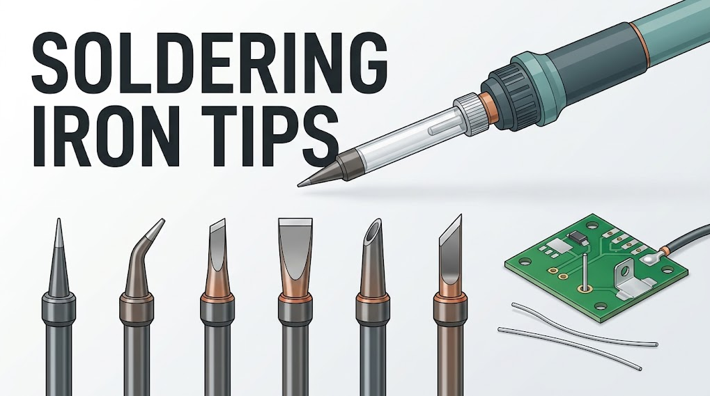
Soldering Iron Tips Guide: Types, Shapes, and Best Uses
Soldering iron tips are the working surfaces that transfer heat from a soldering tool into a component lead, pad, wire, or terminal. The best tip is not automatically the smallest or sharpest. It is the largest shape that fits the joint safely, creates a stable contact patch, and belongs to the correct cartridge or handpiece system.This guide is for electronics hobbyists, repair technicians, production teams, educators, and buyers comparing tip ranges. It explains common soldering tip shapes, how size changes heat transfer, when conical, chisel, bevel, and knife tips work best, how T12, C210, and C245 ecosystems differ, and how to keep a tip wettable without damaging its plating.
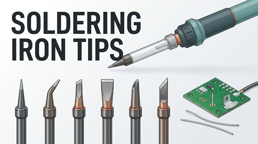
Key Takeaways
- Choose the largest tip that safely fits the pad, lead, or terminal and surrounding clearance.
- A flat chisel face usually transfers heat more efficiently than a needle point on through-hole joints, wires, connectors, and copper planes.
- Fine conical and bent tips are useful when access is limited, but a small contact patch can slow wetting and tempt the operator to use excessive temperature or dwell time.
- Bevel tips can hold a controlled solder reservoir for drag work and broad terminals; knife tips offer a long edge for selected pin rows and edge contacts.
- Tip shape names are not universal dimensions. Confirm width, reach, angle, cartridge family, handpiece, controller support, and electrical compatibility.
- Keep the working face tinned, use the maker-approved cleaning method, and use sleep or standby functions when available. Replace tips with exposed base metal, holes, cracks, or persistent non-wetting surfaces.
Table of Contents
- What are soldering iron tips?
- How does tip shape affect heat transfer?
- Which soldering tip shape should you use?
- How do you match tip size to the joint?
- Which tips work best for common electronics jobs?
- How do T12, C210, and C245 tips differ?
- How should you care for soldering iron tips?
- What common mistakes shorten tip life?
- What should buyers compare?
- Frequently asked questions
What Are Soldering Iron Tips?
A soldering iron tip is the plated metal interface between the heater and the solder joint. Traditional irons may use a separate replaceable tip over a heater. Cartridge systems place the heater and temperature-sensing elements closer to the working end. Either design must move energy through the tip coating, the wetted solder film, and the joint surfaces.The working face is normally engineered as a layered component rather than bare copper. Copper conducts heat well, while iron plating provides a surface that resists rapid dissolution in molten solder. Additional barrier and outer coatings protect non-working areas and control where solder wets. Construction varies by manufacturer, so filing or grinding a plated tip can expose the core and permanently shorten its life.
TWI's overview of how soldering joins materials without melting the base parts is useful context for understanding the tip's job. The tip heats the work and solder; it is not itself the filler metal or the joint.
Quick soldering tip selection table
| Tip shape | Best starting use | Heat-transfer behavior | Main limitation |
|---|---|---|---|
| Fine conical | Tiny isolated pads and access-limited points | Small contact patch and low obstruction | Weak choice for planes, large leads, and terminals |
| Bent conical | Crowded pads viewed under magnification | Reaches around nearby parts | Side loading and small contact can reduce repeatability |
| Chisel | Through-hole leads, wires, pin rows, general repair | Flat face creates efficient contact | Must be oriented correctly on the joint |
| Wide chisel | Shields, large pads, connectors, ground planes | Broad contact moves heat quickly | Oversizing can touch plastic or adjacent features |
| Bevel or hoof | Drag soldering, solder transfer, broad terminals | Face can carry a controlled solder reservoir | Excess solder can bridge fine leads |
| Knife or blade | Selected pin rows, edge contacts, rework access | Long edge contacts several points | Poor fit in recessed or tightly surrounded joints |
How Does Tip Shape Affect Heat Transfer?
Heat flows well when three conditions occur together: the tip has enough thermal capacity for the load, the station can replace lost energy, and the wetted contact patch is broad and stable. A sharp point may look precise, but only a very small part of the point touches a flat pad or round lead. A chisel face can touch both surfaces at once and form a larger solder bridge.The practical rule is simple: contact area first, temperature second. If a joint will not wet, first check tip cleanliness, tinning, flux, geometry, and recovery. Raising the setpoint can accelerate oxidation, damage flux, soften plastic, lift pads, and stress components without fixing a poor contact path.
The Adafruit guide to building a soldering toolkit also treats an appropriate temperature-controlled iron and supporting tools as a system choice. Tip selection works the same way: geometry cannot compensate for an underpowered or unstable controller, and a powerful station cannot make an oxidized needle point efficient on a large terminal.
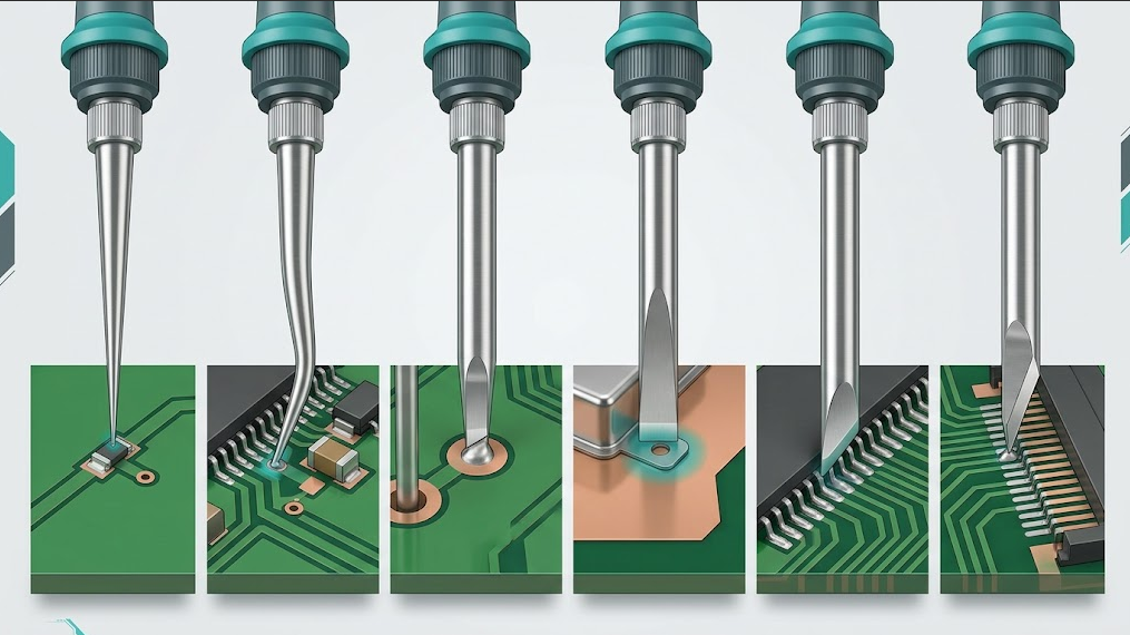
Which Soldering Tip Shape Should You Use?
Conical tips for access-limited work
A conical tip narrows to a point. It is useful for tiny isolated pads, bodge wires, and locations where a wider face would touch nearby components. The operator can approach from several angles, which helps during inspection work under magnification.Do not select a fine cone merely because the component is small. If the pad is connected to a copper pour or the lead is relatively large, the tiny contact point may lose heat faster than the station can restore it at the joint. A small chisel often provides better control because it wets a flat face rather than a theoretical point.
Bent conical tips for awkward angles
A bent conical tip moves the working point away from the handpiece axis. That can improve visibility or reach behind a connector. It is a specialized access tool, not a universal precision upgrade. Side pressure can reduce contact consistency, and the narrow end still has limited thermal contact.Chisel tips for most general electronics work
A chisel tip has a flat rectangular working face. For many through-hole pads, connector pins, wires, and general repair joints, it is the best starting shape. The flat face can touch the lead and pad together, creating a short, predictable heat path.Select a face approximately suited to the available metal area, then orient that face toward both parts of the joint. A medium chisel usually gives more usable precision than a fine cone because the joint heats promptly and the operator can leave sooner.
Wide chisel tips for planes, shields, and terminals
A wider chisel carries more metal near the working face and creates a larger contact patch. It is useful for shield tabs, large connector pins, thick wires, terminal blocks, and pads tied to substantial copper. The correct wide chisel can complete the joint faster at a moderate setting than a fine tip held on the work for a long time.Clearance is the limit. The tip must not contact nearby plastic, solder mask, or small components. If the board is very heavy, preheating within the assembly's approved process window may be safer than continuing to increase tip size or temperature.
Bevel or hoof tips for solder delivery and drag work
A bevel tip presents an angled oval or circular face. Its face can hold a small solder reservoir, making it useful for drag soldering pin rows, tinning wire, and feeding solder across a broad terminal. The operator controls both heat and solder volume with one wetted surface.Too much solder on the face can bridge adjacent leads. Use suitable flux, keep the face clean and tinned, and validate the motion on representative scrap before touching a valuable assembly.
Knife tips for long edges and selected rework
A knife or blade tip provides a long working edge and an angled point. It can address rows of leads, edge contacts, and selected rework tasks where a conical tip cannot produce enough line contact. It is less suitable for recessed joints or boards crowded with heat-sensitive plastics.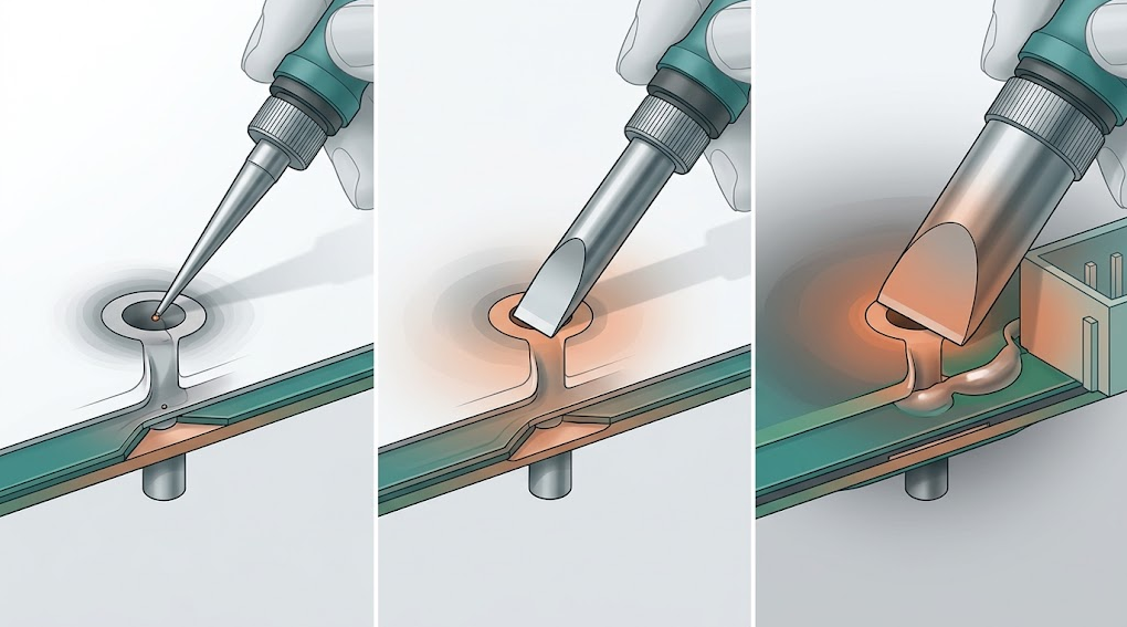
How Do You Match Tip Size to the Joint?
Use the joint's accessible metal area, not the component's marketing category, as the starting point. Two through-hole connectors can behave differently when one pad is isolated and the other is tied to several internal ground layers.Follow this six-step check:
- Identify both surfaces. The tip should heat the component lead and the pad, wire and lug, or shield and land together.
- Check clearance. Note nearby plastic, solder mask, components, cables, and conformal coating.
- Start with the largest safe face. Select a chisel, bevel, or blade that fits the exposed metal without touching adjacent features.
- Tin the working face. A thin solder film improves the thermal bridge; a dry oxidized surface does not.
- Test on representative work. Use a scrap assembly or controlled coupon with similar copper and metal mass.
- Record the process. Capture cartridge part number, face width, setpoint, alloy, flux, preheat condition, contact time, and joint result.
| Observation | Likely cause | Better next check |
|---|---|---|
| Solder melts on the tip but not on the joint | Contact area is too small, surfaces are oxidized, or the joint is drawing heat away | Re-tin, add suitable flux, use a broader face, and confirm recovery |
| Pad wets but the lead does not | Tip touches only the pad | Reorient a chisel to contact pad and lead together |
| Plastic softens before solder flows | Tip is oversized, dwell is too long, or the setting is excessive | Reduce collateral contact, improve geometry, and validate a lower-risk process |
| Tip temperature collapses repeatedly | Thermal load exceeds the useful tip and station combination | Use a larger supported cartridge, check power delivery, or preheat safely |
| Fine-pitch leads bridge | Solder reservoir or face width is excessive for the motion | Reduce solder volume, use flux, change geometry, and practice on scrap |
Which Tips Work Best for Common Electronics Jobs?
| Electronics task | Recommended starting geometry | Why it works | When to change |
|---|---|---|---|
| Small isolated SMD pad | Fine conical or small chisel | Fits limited space | Move to a small chisel if wetting is slow |
| Through-hole resistor or header | Small or medium chisel | Contacts pad and lead together | Use a wider face when the pad connects to a plane |
| Fine-pitch drag soldering | Small bevel or knife | Provides a controlled wetted edge | Use less solder or a smaller face when bridging persists |
| Connector shield tab | Wide chisel | Broad contact matches the metal area | Consider safe preheat for very large ground structures |
| Thick wire to lug | Chisel or bevel | Transfers heat and supports solder delivery | Increase supported tip mass before increasing setpoint |
| Large ground-plane pad | Wide chisel or higher-capacity supported cartridge | Reduces thermal resistance at the joint | Check station recovery and board limits if wetting remains slow |
| Rework beside tall parts | Bent conical, small chisel, or knife | Improves access and visibility | Choose a less obstructed angle before using side pressure |
This table is a starting point, not a temperature recipe. Solder alloy, flux chemistry, board finish, copper thickness, component limits, preheat, ventilation, and operator technique all affect the final process.
How Do T12, C210, and C245 Tips Differ?
T12, C210, and C245 refer to different cartridge ecosystems. They should not be ranked only by physical size, and they are not interchangeable merely because two cartridges can be inserted into similar-looking handles.| Cartridge family | Typical selection emphasis | Useful starting jobs | Compatibility boundary |
|---|---|---|---|
| T12 | Broad general-purpose shape availability | Bench repair, through-hole, wires, and many common SMD tasks | Confirm station, handle, contact arrangement, sensor interpretation, supply, and grounding |
| C210 | Compact geometry and access | Fine-pitch, microscope work, small pads, and dense assemblies | Requires explicit controller and handpiece support for the exact cartridge arrangement |
| C245 | General work through heavier thermal loads | Connectors, planes, shields, terminals, and larger pads | Requires supported cartridges, handle, power delivery, firmware profile, and protective grounding |
Browse QUICKO's T12 soldering tip range to compare available shapes within one ecosystem. QUICKO also lists black-finish T12 tip options; finish names and appearance do not replace dimensional, plating, wetting, and station-compatibility checks.
For a controller example that names more than one cartridge family, see the QUICKO C210/C245 cordless soldering station listing. Treat its voltage, battery, included-tip, and performance details as model-specific.
Cartridge compatibility checklist
- Exact cartridge family and part number
- Handle model, insertion depth, retention, and cable
- Heater and sensor contact arrangement
- Controller firmware or selected cartridge profile
- Input voltage, polarity, current capability, and connector rating
- Tip-to-ground path and ESD requirements
- Stand, sleep sensor, and cartridge-change procedure
- Manufacturer-approved calibration and cleaning method
How Should You Care for Soldering Iron Tips?
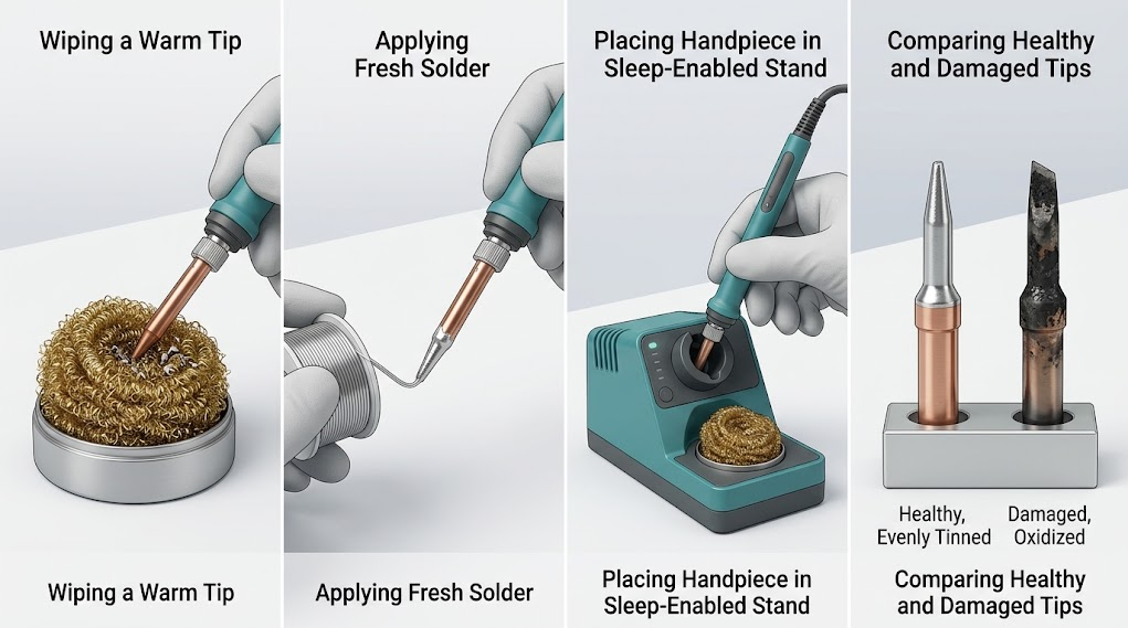
Tip life depends on temperature, idle time, alloy, flux activity, cleaning method, and how consistently the working face stays tinned. A simple routine prevents many premature failures.- Use the lowest effective validated setpoint. Avoid leaving the tool at a high working temperature between joints.
- Clean lightly. Use brass wool, a damp sponge, or another method approved for the exact tip system. Aggressive abrasion can remove protective plating.
- Re-tin immediately. Apply a thin fresh solder coat after cleaning and before returning the handpiece to its stand.
- Use sleep or standby. When supported, verify that the stand triggers the expected temperature reduction and wake behavior.
- Store the face protected. Leave a visible solder coating on the working surface when shutting down, following the manufacturer's procedure.
- Replace damaged tips. Retire a tip with cracks, holes, exposed core metal, distorted geometry, unstable temperature behavior, or a working face that will not wet after approved recovery steps.
Safety note
Soldering involves hot surfaces, molten metal, flux fumes, electrical equipment, and sometimes lead-containing solder. Use appropriate local exhaust or ventilation, eye protection, heat-safe workholding, and hygiene controls. Wash hands after handling lead-containing materials and keep food and drink away from the bench. The U.S. Environmental Protection Agency's lead information and exposure-reduction resources provide general lead-hazard context; workplace procedures must follow applicable local regulations and the safety data sheets for the actual solder and flux.What Common Mistakes Shorten Tip Life?
Using a needle point for every job
A tiny point can force longer contact times on ordinary through-hole and connector work. The operator may compensate with a higher setpoint, which accelerates oxidation while the joint still receives heat inefficiently. Keep at least one general-purpose chisel available.Filing a plated tip
Many soldering iron tips use protective iron plating over a conductive core. Filing may expose the core, after which molten solder can erode it rapidly. Follow only the cleaning and restoration methods approved for the exact tip.Leaving the tip dry
An unprotected hot working face oxidizes quickly. A thin solder coat limits direct exposure to air and keeps the face ready to form a thermal bridge at the next joint.Treating maximum temperature as performance
A high displayed number is not proof of fast heat transfer. Tip size, contact, wetting, heater location, sensing, power delivery, and controller response determine what happens at the joint.Mixing cartridge families by appearance
Mechanical fit does not prove electrical compatibility. A mismatched heater or sensor arrangement can produce inaccurate temperature control, faults, damage, or unsafe operation. Use only documented combinations.What Should Buyers Compare?
Use this checklist when comparing a tip range or complete soldering system:- Shape coverage: fine access tips, small and medium chisels, broad thermal tips, bevels, and specialized blades where needed
- Dimensions: working-face width, reach, bend, shaft diameter, and clearance around real assemblies
- Cartridge system: explicit support for the intended controller and handpiece
- Thermal fit: enough contact area and cartridge capacity for representative joints
- Surface quality: even plating, consistent wetting, and clear replacement criteria
- Availability: stable access to the exact high-use shapes and spare cartridges
- Traceability: part numbers, manuals, specifications, and batch or supplier records needed by the organization
- Standby support: stand sensing, sleep temperature, wake behavior, and cartridge-change method
- Safety and grounding: verified protective-earth or tip-ground path and ESD suitability for the workspace
- Process validation: ability to document the station, tip, setpoint, alloy, flux, preheat, and acceptance result
Frequently Asked Questions
What is the best all-purpose soldering iron tip?
A small or medium chisel is the best general starting point for many electronics benches. Its flat face can contact a pad and lead together, so it often heats through-hole joints, wires, and connectors faster than a fine cone. The correct width still depends on clearance, copper area, and station compatibility.Is a conical or chisel soldering tip better?
A conical tip is better when access is extremely limited and only a tiny contact point is safe. A chisel is usually better for general electronics because its flat face transfers heat more efficiently. Choose by the joint's accessible metal area, not by the assumption that a sharper point is always more precise.What soldering tip should I use for circuit boards?
Use a small chisel for most through-hole and ordinary SMD joints, a fine conical or bent tip for crowded access, a bevel or knife for validated drag work, and a wider chisel for ground-connected pads or shields. Confirm that the tip belongs to the board-safe, grounded cartridge system used at the bench.Why will solder not stick to my iron tip?
The working face may be oxidized, contaminated, damaged, too cool, or missing a fresh solder coating. Apply the maker-approved cleaning method, suitable flux, and fresh solder. If the face still repels solder or shows holes, cracks, exposed core metal, or distorted plating, replace the tip rather than filing it.Are T12, C210, and C245 soldering tips interchangeable?
No. T12, C210, and C245 identify different cartridge ecosystems with different mechanical and electrical requirements. Similar appearance or insertion does not prove compatibility. Verify the exact controller, firmware profile, handpiece, contacts, supply, grounding, cartridge part number, and manufacturer instructions before powering any combination.Conclusion
Choosing soldering iron tips is a contact-area and compatibility decision. Start with the joint: identify both surfaces, note nearby hazards, and choose the largest safe working face. For most general electronics work, a small or medium chisel is the practical baseline. Add conical, bevel, knife, or wide thermal shapes only when access, solder delivery, or joint mass makes them useful.Then validate the complete system. Confirm the cartridge family, handle, controller, supply, grounding, and cleaning method; test on representative work; and record the setup. A well-matched, clean, tinned tip can deliver faster joints with less dwell than a sharp but poorly contacting point.
Sources and Evidence Boundaries
- TWI: What Is Soldering? A Full Guide, accessed August 20, 2026. Used for general process context, not QUICKO product claims.
- Adafruit Guide to Excellent Soldering: Tools, accessed August 20, 2026. Used for general electronics toolkit and station context.
- U.S. Environmental Protection Agency: Lead, accessed August 20, 2026. Used only for general lead-hazard context.


Linkedin:


