
 Tel:+86-13713635953
 Email:support@quicko.com.cn


How Do T12 Soldering Iron Tips Integrate the Heater and Sensor?
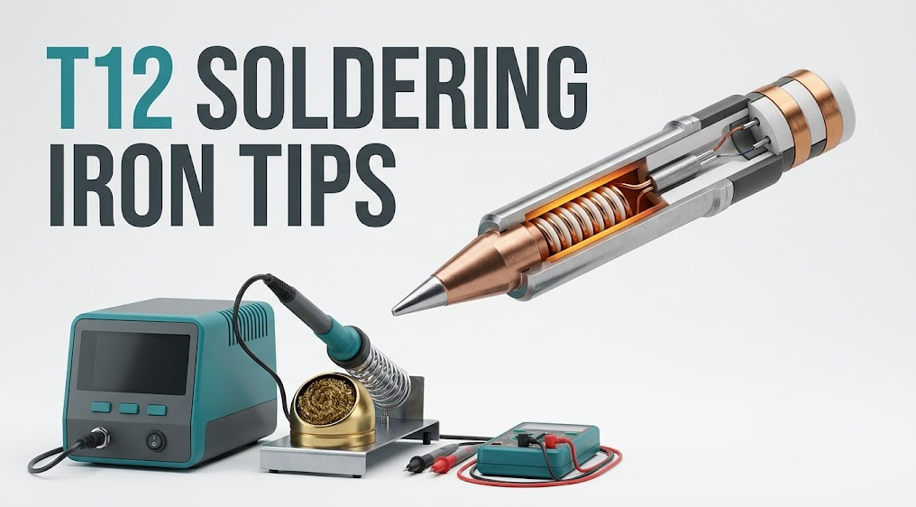
How Do T12 Soldering Iron Tips Integrate the Heater and Sensor?
T12 soldering iron tips are cartridge assemblies that place the working tip, heating element, and temperature-sensing function inside one replaceable thermal unit. Bringing the heater and sensor close to the tip reduces the number of material interfaces between heat generation, temperature measurement, and the solder joint. The station reads feedback from the cartridge, estimates tip temperature, and switches or modulates heater power to hold the selected setpoint.That is the structural principle, not a universal wiring specification. Cartridge resistance, sensor behavior, contact assignment, calibration, mechanical tolerances, and controller algorithms can vary. A cartridge that fits a handle is not automatically electrically compatible, accurately calibrated, or safe to use.
Commercial disclosure: QUICKO publishes this guide and sells soldering stations, controllers, handles, cartridges, tips, and accessories. QUICKO links are commercial references. No unverified QUICKO model specification or universal T12 interchangeability claim is made here.
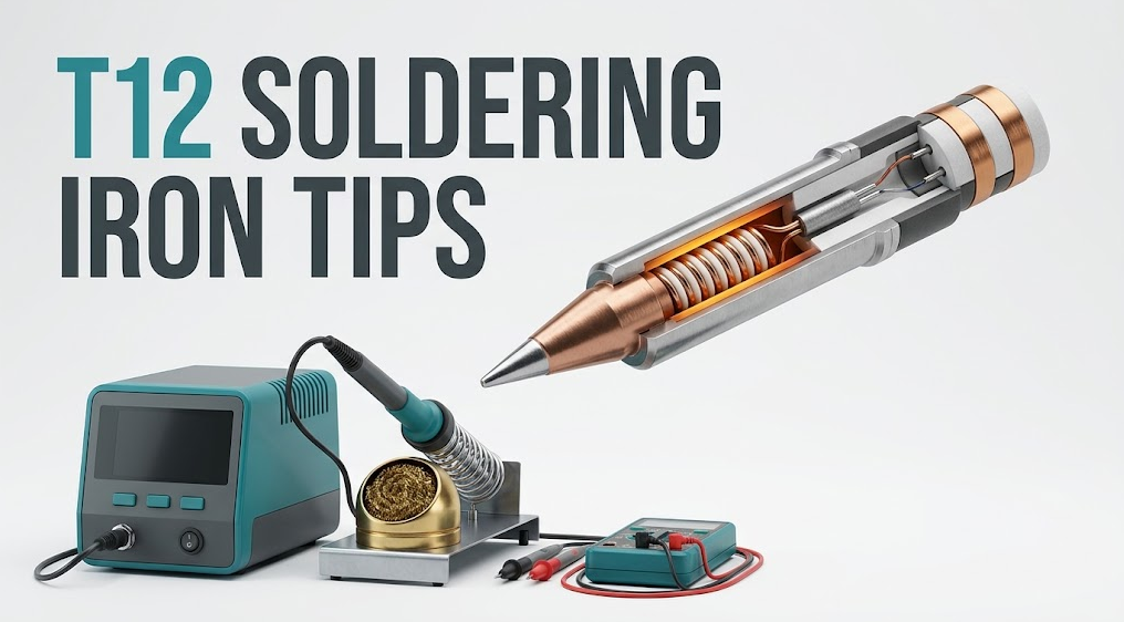
Quick Answer: What Is Integrated in a T12 Cartridge?
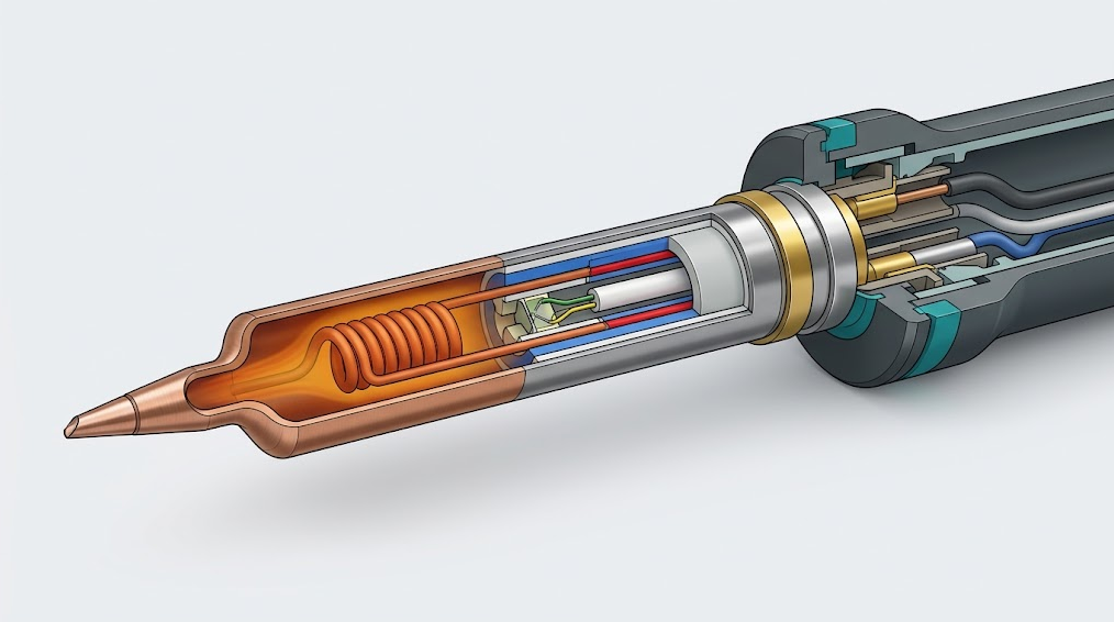
A T12 cartridge integrates three functional layers: a metal working tip that transfers heat to the joint, an electric heater positioned close to that tip, and a temperature-sensing path that lets the controller estimate thermal state. Insulation keeps the intended electrical paths separated, while rear contacts connect the assembly to the handle and controller. The controller closes the loop by comparing feedback with the setpoint and adjusting heater power.What Is Inside a T12 Cartridge?
The HAKKO explanation of its composite-tip construction describes a soldering tip integrated with a heating element and sensor. That manufacturer statement supports the central concept: the consumable is more than a shaped piece of copper or plated metal. It is a small electrothermal assembly.| Functional region | What it does | What it does not prove |
|---|---|---|
| Working tip and plating | Stores and transfers heat to solder, pad, lead, or thermal mass | The tip shape alone does not establish heater power or compatibility |
| Integrated heater | Converts controlled electrical power into heat close to the working end | Cold resistance alone does not prove the heater is healthy under load |
| Temperature-sensing path | Produces a signal the controller interprets as temperature feedback | The sensor type or signal scale cannot be assumed across all cartridges |
| Electrical insulation | Separates conductors and helps direct heat through the intended structure | An intact outer tube does not prove internal insulation is undamaged |
| Metal body and locating features | Supports insertion, alignment, heat flow, and retention in the handle | Similar geometry does not guarantee identical tolerances or contact order |
| Rear contacts | Carry heater power, feedback, or shared electrical functions to the controller | The number or appearance of bands does not reveal a universal pinout |
In a conventional iron with a separate replaceable tip, heat must cross interfaces from the heater to a sleeve or barrel and then into the tip. Every interface adds contact pressure, surface condition, geometry, and thermal resistance to the path. A cartridge reduces those interfaces by packaging the active components together. That can improve response, but performance still depends on controller power, contact quality, calibration, tip geometry, plating condition, workload, and firmware.
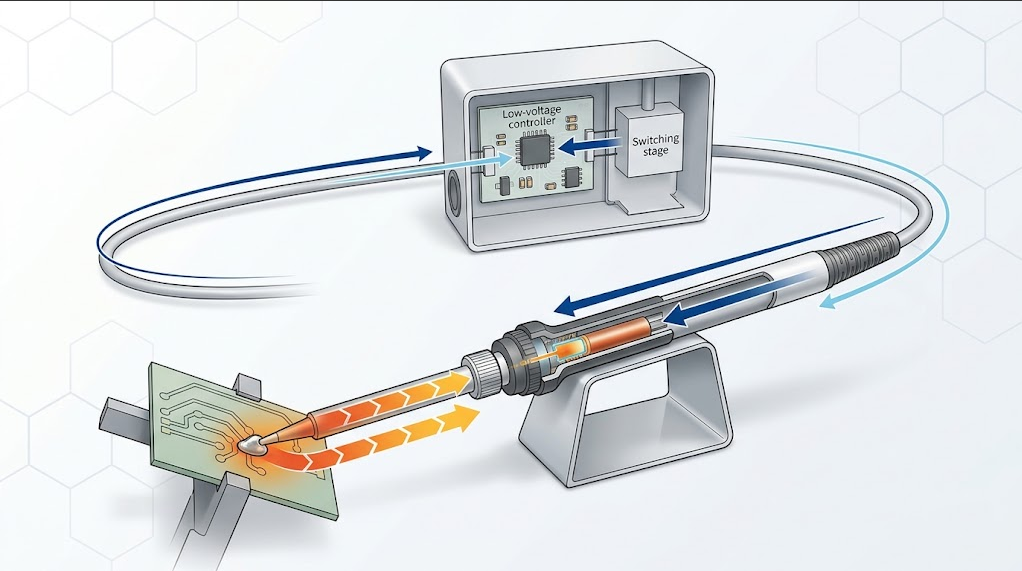
How Does the Heater-and-Sensor Control Loop Work?
The station does not simply apply constant power and hope the tip reaches the correct temperature. A temperature-controlled system repeatedly measures, decides, and heats.- Setpoint: The operator selects a target temperature appropriate for the solder, flux, components, board, and process.
- Measurement: The controller samples the cartridge's sensing signal through the handle contacts.
- Interpretation: Electronics and firmware convert that signal into an estimated temperature using the system's expected sensor behavior and calibration.
- Comparison: The controller compares the estimate with the setpoint and its control thresholds.
- Power command: A switching stage supplies, reduces, or interrupts heater power according to the control algorithm and protection state.
- Thermal response: Heat travels from the integrated heater into the tip and then into the joint. A large ground plane or connector shell can remove heat rapidly.
- Feedback: The sensor detects the changed thermal state, and the cycle repeats.
For examples of available geometries, browse the QUICKO T12 tip collection. Treat the category as product discovery rather than compatibility proof: a cartridge and controller still form one documented and calibrated system.
Integrated Cartridge Versus a Separate Tip and Heater
| Design question | Integrated T12-style cartridge | Separate tip, heater, and sensor arrangement |
|---|---|---|
| Thermal path | Heater and sensor are packaged near the working end | Heat may cross more sleeves, gaps, or contact interfaces |
| Service action | Replace the active thermal cartridge as a unit | Replace the passive tip or service heater and sensor separately |
| Contact sensitivity | Cartridge contacts and handle pressure directly affect power and feedback | Heater connections may remain fixed when only the tip is changed |
| Calibration sensitivity | Controller expectations must match the cartridge's electrical behavior | Sensor and heater remain tied to the iron body, though tip fit still matters |
| Consumable cost | The cartridge includes active components and is more than a metal tip | A passive replacement tip can be simpler |
| Diagnosis | Requires separation of contact, heater, sensor, controller, and calibration faults | Mechanical tip fit and fixed-heater condition can be checked separately |
The integrated design is not automatically superior for every task. It favors quick cartridge changes and a short thermal path. A separate system may favor low-cost passive tips or different service practices. Selection should follow joint size, access, duty cycle, traceability, available shapes, controller support, maintenance policy, and total operating cost.
Which Parameters Change Heating and Temperature Behavior?
Tip Geometry and Thermal Mass
A fine conical tip has less contact area than a chisel or bevel of comparable construction. It may feel fast in free air but transfer heat poorly to a large pad. A larger geometry can store and deliver more heat, yet it also creates a larger load during startup. Match the contact face to the joint rather than compensating for a poor geometry with an unnecessarily high setpoint.Heater Power and Supply Limits
The controller can only deliver the power supported by its supply, switching stage, cable, handle, contacts, and protection design. Do not infer cartridge wattage from a marketplace title or assume that a higher-rated controller will safely drive every cartridge. Use the station and cartridge documentation as one compatibility set.Sensor Method and Calibration
Different systems can interpret resistance, thermoelectric voltage, or other temperature-dependent behavior differently. The controller's analog front end and firmware must expect the cartridge's signal. A stable but wrong reading is possible when the electrical behavior and calibration do not match. Compare against a documented reference method before calling a display accurate.Contact Resistance and Mechanical Fit
Oxidation, contamination, weak spring pressure, wear, poor dimensional tolerance, or incomplete insertion can add resistance or interrupt feedback. Symptoms can include slow heat-up, intermittent heating, temperature jumps, error messages, or failure to recognize the cartridge. Replace damaged parts; do not wedge, bend, short, or shim contacts to force operation.Joint Load and Technique
Temperature recovery is a system response to heat leaving the tip. Joint mass, copper area, component leads, solder alloy, flux activity, contact time, tip wetting, and operator technique all matter. A fair comparison keeps the station, setpoint, tip geometry, solder, joint coupon, and timing constant.Why a Cold Resistance Reading Is Not a Universal Identity Test
A multimeter can sometimes reveal an open circuit or gross short, but a single cold-resistance number cannot identify every cartridge or prove compatibility. The meter sees only the electrical path created by the contact pair you selected, the test current, lead resistance, contact pressure, and ambient temperature. Heater and sensing functions may share conductors or be interpreted dynamically by the controller.Keep two questions separate:
- Heater-circuit screening: Is the manufacturer-defined heater path open, shorted, or within the specified cold range for this exact cartridge and temperature?
- Sensor verification: Does the specified sensing signal change correctly with temperature and match the controller's documented input method?
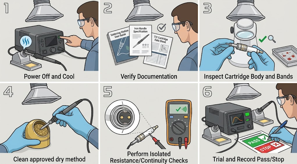
A Safe Inspection and Test Workflow
Use the exact HAKKO T12/T15 manual and maintenance index as an example of why instructions must be matched to a named station, handle, region, and tip series. For QUICKO equipment, use the current QUICKO manual or support record for the exact product.- Power off, unplug, and cool. Return the iron to its stand, disconnect the supply, and allow the cartridge and handle to reach a safe temperature.
- Freeze the configuration. Record station, firmware, handle, cartridge marking, tip shape, setpoint, supply, cable, sleep settings, and fault symptoms.
- Verify documentation. Confirm the approved cartridge family, insertion method, contact definition, test limits, cleaning method, and replacement procedure.
- Inspect without modification. Check the shaft, plating, locating features, insulation, contact bands, handle socket, cable, and strain relief. Stop for cracks, looseness, deformation, corrosion, discoloration, or exposed conductors.
- Clean only as approved. Remove loose contamination by the manufacturer's method. Do not grind contacts, scrape insulation, apply unknown chemicals, or force a cartridge into a socket.
- Measure only defined isolated paths. If the manual provides contact pairs and ranges, use a suitable meter on the unpowered, disconnected assembly. Compensate for lead resistance when the specified values require it.
- Reassemble and run a controlled trial. Use a nonflammable bench, eye protection, fume extraction, a stable stand, and a representative practice joint. Observe startup, stability, recovery, errors, and abnormal heating.
- Record pass or stop. Repeat a defined load before accepting a replacement. Stop immediately for uncontrolled heating, unexpected output, odor, smoke, hot contacts, insulation damage, repeated faults, or exposed conductors.
Troubleshooting Symptoms Without Guessing the Pinout
| Symptom | Plausible causes | Controlled next check |
|---|---|---|
| Station does not recognize the cartridge | Incomplete insertion, contaminated or worn contacts, open path, wrong cartridge family, handle fault | Power off; verify model compatibility and insertion; inspect cartridge and socket |
| Displayed temperature jumps | Intermittent feedback contact, damaged cartridge, cable or handle fault, controller input fault | Freeze configuration; substitute one documented known-good component at a time |
| Slow heat-up | Poor contact, limited supply, mismatched controller, damaged heater, high-load tip or joint | Verify supply and exact cartridge family; compare with a controlled reference load |
| Reaches setpoint but performs poorly | Tip geometry too small, oxidized or unwetted working face, heavy copper load, calibration error | Clean and tin by approved method; use a suitable geometry; verify temperature independently |
| Overshoots or heats uncontrollably | Lost feedback, incompatible sensor behavior, controller or switching fault | Stop, disconnect, quarantine the assembly, and refer it for qualified service |
| Cartridge or handle becomes abnormally hot | Excess contact resistance, poor fit, overload, insulation or connection damage | Stop, disconnect, cool, inspect, and replace the suspect part; do not continue testing |
Change one variable at a time. Swapping the cartridge, handle, controller, supply, and setpoint together may restore operation, but it does not identify the fault. Community threads such as the r/soldering T12 search results are useful for collecting symptom vocabulary; their proposed resistance values, pinouts, and compatibility claims still require manual-level verification.
Compatibility and Procurement Checklist
Before buying or approving a T12 cartridge lot, record:- Exact station and handle models, hardware revisions, firmware, region, and connector system
- Manufacturer-approved cartridge family and the distinction, if any, between T12 and T15 naming
- Mechanical length, diameter, locating features, insertion depth, retention, and contact-band geometry
- Documented heater path, sensor method, contact functions, cold test conditions, and allowed tolerances
- Controller supply, protection, sleep, calibration, error-detection, and grounding requirements
- Required tip shapes, plating, wettable-face dimensions, temperature range, workload, and duty cycle
- Lot traceability, incoming-inspection method, warranty, returns, replacements, and technical support
- Sample-test plan covering recognition, startup, controlled joint load, recovery, stability, contact condition, and repeatability
Frequently Asked Questions
Does every T12 cartridge contain both a heater and sensor?
The defining composite-cartridge concept integrates the tip, heater, and temperature-sensing function, but the internal circuit and construction can vary. Confirm the exact manufacturer documentation. A seller's use of “T12 compatible” is not sufficient evidence of sensor method, quality, calibration, or interchangeability.Are T12 and T15 the same?
They are often associated with closely related cartridge families, and naming can vary by market or document. Do not treat the labels as a universal interchangeability guarantee. Match the station, handle, cartridge series, region, manual, mechanical fit, electrical behavior, and calibration requirements.Why does an integrated heater improve recovery?
Placing the heater close to the working tip reduces intermediate thermal interfaces and lets heat reach the joint through a shorter path. Feedback is also measured near the active assembly. Recovery still depends on controller power, tip geometry, contact condition, calibration, joint mass, soldering technique, and supply limits.Can I identify a T12 cartridge by resistance?
Not reliably from one number. A measurement depends on the selected contacts, meter leads, ambient temperature, internal circuit, and manufacturer specification. Use resistance only for a defined, unpowered screening procedure. Sensor function and operating compatibility require separate verification.Can I test the sensor with a continuity buzzer?
A continuity buzzer may only indicate that some conductive path exists. It does not identify the sensor type, show its temperature response, validate calibration, or prove safe operation. Follow the exact service procedure and use suitable measurement equipment.Why does the station show the setpoint while the joint still solders poorly?
The display is the controller's estimate, not a direct measurement of the solder joint. Poor tip geometry, inadequate wetting, oxidation, a large copper plane, weak contact, calibration mismatch, or technique can limit heat transfer even when the displayed temperature appears stable.Is a cartridge safe if it fits the handle?
Mechanical fit is only one requirement. The cartridge must also match the contact layout, electrical behavior, controller input, heater drive, calibration, protection strategy, and operating limits. Stop if insertion requires force or if the station behaves abnormally.When should I replace rather than troubleshoot a cartridge?
Replace or quarantine it when the body, plating, insulation, contact bands, or locating features are cracked, loose, deformed, deeply corroded, or discolored; when faults repeat after documented checks; or when uncontrolled heating, odor, smoke, hot contacts, or exposed conductors appear.Conclusion
T12 soldering iron tips achieve fast, controllable heating by packaging the working tip, heater, and sensing function into one replaceable cartridge and connecting that assembly to a closed-loop controller. The short thermal path is only half the system: reliable results also require correct contacts, a matching controller, documented sensor behavior, adequate power, calibration, suitable tip geometry, and controlled technique.Treat a T12 cartridge as an electrothermal component, not a universally interchangeable metal tip. Verify the exact documentation, inspect and measure only while de-energized, change one variable at a time, and stop for any sign of lost control or electrical damage.


Linkedin:


