
 Tel:+86-13713635953
 Email:support@quicko.com.cn


C245 Soldering Station Guide for High-Thermal-Mass Work
C245 Soldering Station Guide for High-Thermal-Mass Work
A C245 soldering station is a cartridge-based temperature-controlled system designed for general electronics work and joints that demand more sustained heat transfer than a small precision tool can comfortably deliver. The format is especially useful for ground planes, shield tabs, large connectors, terminal blocks, and thick wires, but performance depends on the complete system: cartridge, tip geometry, handpiece, controller, power supply, stand, and process.This guide is for repair technicians, production operators, advanced hobbyists, and buyers comparing C245-compatible equipment. It explains how thermal load changes a soldering job, how to select a tip, how to check compatibility, and how to test recovery without relying on a seller's largest wattage or temperature number.
|
Commercial disclosure QUICKO publishes this guide and sells soldering stations, handles, cartridges, and tips. QUICKO product links are commercial links. Technical principles are separated from model-specific claims, and competitor content was reviewed only to identify common questions and missing decision guidance. |
|---|
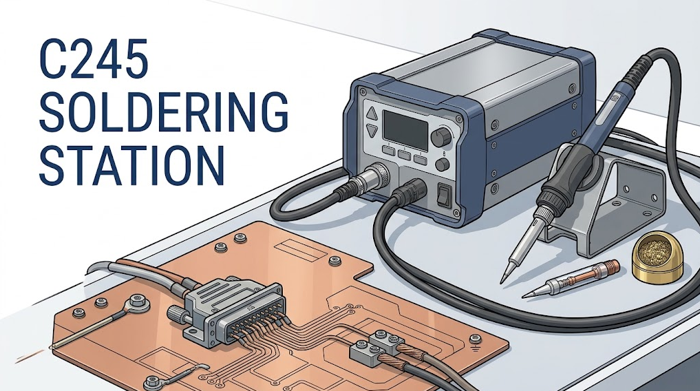
Technical cover illustration of a C245 soldering station, cartridge handpiece, ground plane, heavy connector, and thick wire with C245 SOLDERING STATION shown once.
Key Takeaways
- High-thermal-mass work is a heat-flow problem, not simply a request for a higher temperature setting.
- A C245 cartridge places the working tip, heater, and sensing function close together, while the controller supplies and regulates energy through a compatible handpiece.
- Tip contact area often matters more than a sharp-looking point. A chisel or bevel that matches the joint can transfer heat faster at a lower setpoint.
- Mechanical fit alone does not prove compatibility. Confirm cartridge family, handpiece contacts, controller support, supply limits, grounding, and calibration behavior.
- Compare stations using a repeatable thermal-load test. Record the tip, setpoint, joint or test coupon, recovery time, overshoot, and soldering result.
- Preheating can reduce the load on the iron, but it requires board-specific temperature limits and safe handling procedures.
Table of Contents
- What is a C245 soldering station?
- Why do high-thermal-mass joints challenge an iron?
- How does a C245 system deliver and control heat?
- Which C245 tip shape should you choose?
- What is the difference between C245, C210, and T12?
- How do you verify C245 compatibility?
- How do you set up a C245 station?
- How do you test thermal recovery?
- What faults cause weak heavy-joint performance?
- What should buyers compare?
What Is a C245 Soldering Station?
A C245 soldering station is a controller, power stage, handpiece, and stand designed to operate C245-family cartridges. In JBC's product system, C245 identifies a cartridge range and T245 identifies a compatible general-purpose handle family. Third-party sellers may use the terms "C245 compatible" or "C245 style," but those labels do not establish identical electrical characteristics, contact routing, firmware, plating quality, or safety construction.JBC describes its C245 cartridge range for general soldering as covering both surface-mount and through-hole work. The range includes multiple tip shapes and sizes, which is important because the job is not defined by power alone. A broad shield tab, a connector pin tied to a ground plane, and a thick wire terminal need different contact geometry even when the same station operates all three.
The useful distinction is between precision and thermal capacity. A compact cartridge can improve access around tiny components, while a larger cartridge and handle can provide more contact area and sustained energy for medium and heavy joints. That does not mean C245 should be used indiscriminately on heat-sensitive parts. The station still needs an appropriate tip, setpoint, contact time, flux, and board-specific process window.
For the basic electrical-to-thermal path, QUICKO's soldering iron heating explanation describes how the power source, heater, sensor, tip, and joint interact.
Why Do High-Thermal-Mass Joints Challenge a Soldering Iron?
A high-thermal-mass joint absorbs heat faster than a small joint because more metal and copper are connected to the contact point. A large ground plane spreads energy away from the pad. A metal shield or terminal block stores energy in its own mass. Thick wire conducts heat away from the lug. The station must replace that lost energy while keeping the tip surface hot enough to wet the joint.The important variable is thermal impedance between the heater and the work. A clean, tinned tip with a broad contact patch creates a lower-resistance heat path than a dry fine point touching the joint at one small spot. Fresh solder can form a temporary thermal bridge, while suitable flux removes oxides that otherwise reduce wetting.
Raising the display from 350 C to 450 C may make the first contact feel more aggressive, but it can also accelerate flux breakdown, tip oxidation, pad damage, insulation damage, and component stress. A better sequence is to increase contact area, restore wetting, confirm recovery, preheat when appropriate, and only then adjust the setpoint within the materials' process limits.
A practical definition
High-thermal-mass soldering is any joint where the workpiece removes heat from the tip fast enough to delay wetting or collapse the working temperature. The condition depends on copper area, metal volume, tip size, alloy, flux, preheat, contact time, and station recovery. It is not defined by one universal wattage threshold.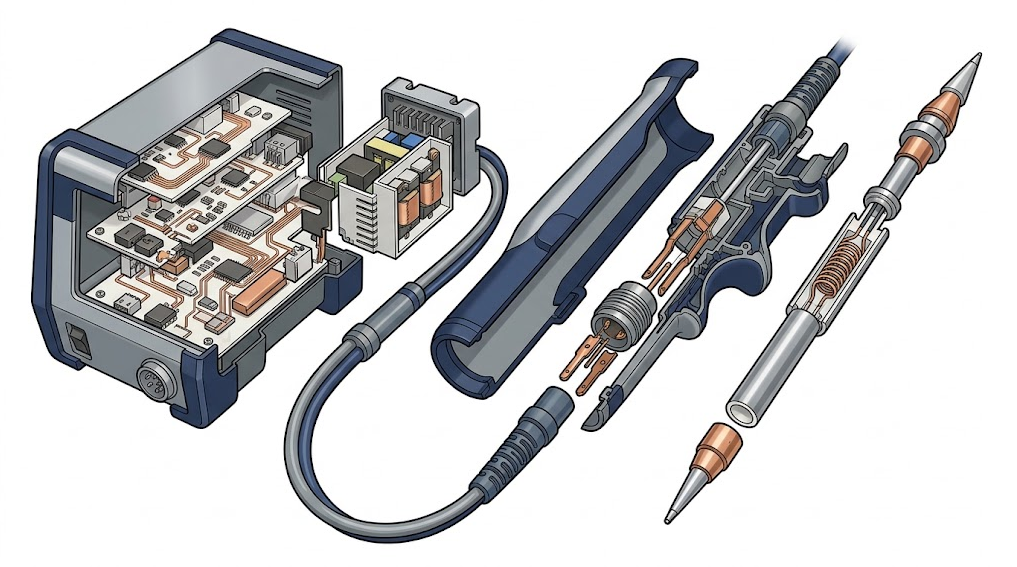
Exploded technical cutaway of a C245-style station, handpiece, contacts, integrated heater and sensor region, and cartridge tip.
How Does a C245 System Deliver and Control Heat?
The controller compares a temperature signal with the selected setpoint and commands the power stage to add heater energy. When the tip touches a heavy joint, the sensed temperature falls. A capable controller increases heater drive, then reduces it as the cartridge approaches the target. The quality of this response depends on sensing, control tuning, available supply power, electrical contacts, cartridge construction, and the thermal path into the joint.Electrical input power can be expressed as `P = V x I`, but the number printed on a station does not show how much useful energy reaches the joint. Cable loss, current limits, duty cycle, heater resistance, connector condition, firmware protection, and supply voltage all affect delivered power. The same nominal rating can produce different recovery behavior in two systems.
JBC's explanation of its soldering heating and sleep system describes fast heating, temperature recovery, sleep, and hibernation within JBC equipment. Treat those statements as manufacturer-specific evidence. Do not assume that every third-party C245-compatible controller uses the same sensor interpretation, control loop, safety limits, or standby behavior.
QUICKO's temperature-controlled soldering station guide provides more background on setpoints, feedback control, and recovery. A display value is a control target, not proof that every point on the joint has reached the same temperature.
Which C245 Soldering Tip Shape Should You Choose?
Choose the largest tip that safely fits the joint and surrounding clearance. The objective is not to cover the entire component. It is to create enough contact area for fast, controlled heat transfer without touching adjacent plastic, solder mask, or components.| Tip geometry | Best fit | Strength | Main caution |
|---|---|---|---|
| Fine conical | Small isolated pads and access-limited points | Precise placement | Small contact patch can struggle on planes and heavy terminals |
| Medium chisel | Through-hole leads, pin rows, and general repair | Predictable flat contact | Orientation matters; the flat face must meet the joint |
| Wide chisel | Shield tabs, larger pads, and ground-connected joints | High contact area and stable heat flow | Can bridge or touch nearby features if oversized |
| Bevel | Drag work, solder transfer, and broad terminals | Holds a small solder reservoir | Requires controlled solder volume and cleaning |
| Knife or blade | Edge contacts and selected drag applications | Long working edge | Poor fit for recessed or tightly surrounded joints |
| High-thermal-capacity variant | Repetitive heavy joints where supported | More stored energy near the work | May heat or cool differently; confirm controller and process support |
The tip surface must be wettable. If solder beads up or retreats from the working face, clean the tip using the station manufacturer's approved method, apply fresh solder and suitable flux, and replace a damaged cartridge. Abrasive filing can remove protective plating and shorten tip life.
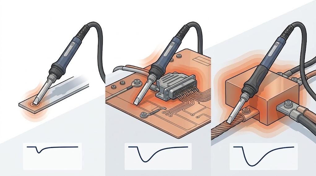
Three-panel comparison of a C245-style handpiece soldering a small pad, a ground-plane connector, and a thick-wire terminal with increasing thermal load.
What Is the Difference Between C245, C210, and T12?
These names identify different cartridge ecosystems, not interchangeable performance tiers. Compare the complete system and job rather than treating one family as universally better.| Family | Typical work profile | Selection advantage | Compatibility boundary |
|---|---|---|---|
| C210 | Fine-pitch, microscope, and access-limited work | Compact handpiece and small tip selection | Requires a controller and handle that explicitly support the relevant C210 arrangement |
| C245 | General electronics through heavier connectors, planes, and terminals | Broad shape range and more contact options for thermal loads | Requires supported C245 cartridges, contacts, power delivery, grounding, and firmware |
| T12 | General cartridge-station work across many common shapes | Widely available controller, handle, and cartridge ecosystem | Pinout, sensor interpretation, supply, handle, and grounding still vary by product |
C210 can be the better tool when access and low obstruction matter most. C245 can be the better fit when the joint repeatedly pulls heat away from a small tip. T12 can cover a broad middle ground depending on cartridge shape and station design. A production bench may use more than one family because changing the handpiece is often faster and safer than forcing one tip to perform every job.
How Do You Verify C245 Compatibility?
Do not insert or power a cartridge until the following items are confirmed from the exact station, handpiece, and cartridge documentation.- Cartridge family: The controller must explicitly support C245, not merely a similar-looking handle.
- Handpiece: Confirm the specified T245 or compatible handle family, insertion depth, retention method, cable, and stand.
- Electrical contacts: Verify heater, sensor, and protective-ground paths. Connector shape alone is not sufficient.
- Supply limits: Match the required input voltage, current capability, polarity, and connector rating.
- Firmware profile: Confirm temperature conversion, fault detection, sleep behavior, and calibration support for the cartridge.
- Grounding and ESD: Verify the tip-to-ground path and the site's ESD-control requirements before working on sensitive electronics.
- Cartridge rating: Check whether the selected standard or high-capacity tip is approved for the controller and process.
The QUICKO C210/C245 cordless product listing is a model-specific example, not a universal C245 specification. The page contains C210 and C245 terminology plus product-specific power, voltage, battery, and included-tip fields. Confirm the exact ordered configuration and manual before combining a controller, battery, handle, or cartridge.
How Do You Set Up a C245 Soldering Station?
Use this commissioning sequence for a new or changed setup:- Inspect before power. Check the cable, connector, stand, cartridge contacts, enclosure, supply, and protective-ground arrangement.
- Confirm the configuration. Match the station model, handpiece, cartridge family, input source, and firmware profile.
- Insert the cartridge cold. Follow the manufacturer's insertion and removal procedure. Never grip a hot cartridge with improvised tools.
- Start conservatively. Select a temperature appropriate for the solder alloy, flux, component, PCB, and approved process rather than beginning at the station maximum.
- Tin the working face. Apply a small amount of fresh solder to create a wettable surface and improve initial contact.
- Test on representative material. Use a scrap assembly or controlled coupon with similar copper and metal mass.
- Verify standby behavior. Confirm sleep, wake, stand detection, and fault response before production use.
- Document the process. Record station, handpiece, cartridge part number, setpoint, solder, flux, preheat condition, and acceptance result.
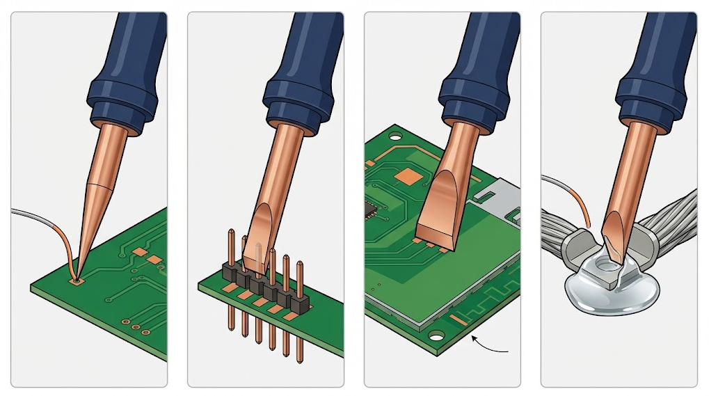
Alt text: Four-zone technical comparison of C245-style conical, medium chisel, wide chisel, and bevel tips matched to different electronic joints.
How Do You Test C245 Thermal Recovery?
A repeatable load test is more useful than a heat-up animation or an unloaded stopwatch. Use a representative coupon or consistent joint, and keep the cartridge, solder, flux, setpoint, preheat, contact method, and measurement method constant.| Test field | What to record |
|---|---|
| Station and supply | Exact model, firmware, input voltage, supply rating, and cable |
| Handpiece and cartridge | Handle model, cartridge part number, shape, width, and condition |
| Process | Solder alloy, wire diameter, flux, setpoint, and preheat condition |
| Thermal load | Coupon material, copper area, connector or terminal mass, and starting temperature |
| Response | Time to wet, displayed dip, recovery time, overshoot, and any fault indication |
| Result | Fillet formation, full wetting, dwell time, damage, residue, and operator notes |
Run several repetitions only after the setup has stabilized. A strong result is not the smallest visible temperature dip. The goal is consistent wetting within an acceptable dwell time, without overshoot, pad damage, burned flux, melted insulation, or excessive tip oxidation.
If a wide tip succeeds at a lower setpoint while a fine point fails at a higher setpoint, the result demonstrates the value of contact area. If both struggle, investigate cartridge condition, power delivery, preheat, joint preparation, and whether the station is correctly configured for the cartridge.
When Should You Preheat the Board or Workpiece?
Preheating is useful when a large board, metal chassis, or ground plane pulls heat away faster than the handpiece can deliver it locally. Raising the whole assembly to a controlled, approved starting temperature reduces the temperature difference the iron must overcome and can shorten tip contact time.Preheat is not permission to heat every board aggressively. Check component ratings, connectors, plastics, adhesives, batteries, displays, conformal coatings, and board warpage risk. Measure at relevant locations, use appropriate ventilation, and follow the equipment and assembly documentation. Never place an unknown powered assembly on a hot plate.
What Faults Cause Weak Heavy-Joint Performance?
| Symptom | Likely causes | Safer next checks |
|---|---|---|
| Tip is hot but solder will not wet | Oxidized tip, contaminated joint, unsuitable flux, or dry contact | Retin the tip, clean the joint, verify materials, and use a broader contact face |
| Display drops and recovers slowly | Undersized tip, supply limitation, worn contacts, wrong cartridge profile, or excessive load | Confirm supply under load, inspect contacts, fit a larger supported tip, and repeat the coupon test |
| Station overshoots after leaving the joint | Control tuning, sensor offset, cartridge mismatch, or measurement artifact | Stop production, confirm cartridge support, calibrate by the approved method, and compare with a known-good cartridge |
| Controller reports a sensor or cartridge error | Poor insertion, dirty contacts, cable damage, wrong handle, or unsupported cartridge | Power down, cool the tool, inspect the approved contact points, and verify the exact configuration |
| Connector or cable becomes warm | Excessive current, damaged connector, loose contact, wrong supply, or poor cable | Disconnect power and do not resume until the electrical path is inspected and corrected |
| Tip oxidizes quickly | Excessive idle temperature, long dwell, aggressive cleaning, or unsuitable chemistry | Enable sleep, reduce unnecessary setpoint and dwell, use approved cleaning, and keep the tip tinned |
Do not bypass a fault, defeat grounding, or increase a current limit to force the station through a heavy joint. A repeated protection event indicates a configuration, supply, cartridge, or process problem that should be diagnosed before work continues.
What Should Buyers Compare Before Ordering?
Compare evidence for the job you actually perform. A useful supplier should be able to identify the exact station, supply, handpiece, cartridge family, included tip, spare parts, calibration method, and warranty path.- Thermal recovery: Ask for a repeatable loaded test, not only no-load heat-up time.
- Cartridge selection: Check the shapes and widths you will use, including replacements that are realistically available.
- Handle ergonomics: Consider grip-to-tip distance, cable flexibility, insertion method, stand fit, and hot-swap procedure.
- Power-source clarity: Confirm included supply, regional plug, grounding, battery compatibility, and current requirements.
- Control behavior: Review sleep, hibernation, presets, calibration, fault detection, and firmware support.
- ESD and grounding: Request measurable specifications and the test method when sensitive electronics are in scope.
- Parts traceability: Confirm cartridge part numbers, production consistency, documentation, and after-sales support.
Frequently Asked Questions
Is a C245 soldering station only for large joints?
No. A C245 station can handle general through-hole and many surface-mount tasks when fitted with an appropriate cartridge. Its advantage is the breadth of contact geometries and capacity for more demanding joints. Very small, access-limited work may still be easier with a compact precision family such as C210.Does a higher wattage make every C245 station better?
No. Wattage describes only part of the electrical capability. Useful performance also depends on the supply under load, heater and sensor arrangement, controller tuning, cable and contact loss, cartridge construction, tip shape, wetting, and the joint. Compare repeatable loaded recovery rather than the largest advertised number.What is the best C245 tip for a ground plane?
A chisel or bevel that safely fits the pad usually creates better contact than a fine conical point. Choose the largest supported working face that avoids adjacent parts. The exact width depends on pad geometry, clearance, copper area, solder alloy, flux, preheat, and the station's recovery behavior.Can C245 and C210 cartridges use the same handle?
Do not assume so. In the JBC system, C245 and C210 cartridges are associated with different handle families. Third-party products may combine support in one controller, but the handle, contacts, firmware profile, supply, and grounding must explicitly match the selected cartridge family.Should I raise the temperature when a heavy joint will not wet?
Check contact area, tip condition, flux, joint cleanliness, supply, cartridge support, and preheat first. A modest setpoint adjustment may be appropriate within the approved process, but a very high setting can burn flux and damage the assembly while failing to fix poor thermal contact.Conclusion
A C245 soldering station is best understood as a controlled heat-delivery system for general electronics and demanding thermal loads. Its practical advantage comes from a compatible cartridge ecosystem, suitable handpiece, broad tip contact, adequate supply, and predictable recovery, not from temperature or wattage alone.Before buying or commissioning a station, map every compatibility field, select a tip that fits the joint, and run a documented load test on representative material. That process gives repair and production teams a defensible answer about whether the system can solder ground planes, connectors, terminals, and thick wires without excessive dwell or heat damage.
Publication Safety Note
Soldering involves hot surfaces, molten metal, fumes, electrical equipment, and potentially lead-containing materials. Work in a ventilated area, use eye protection where appropriate, keep the iron in a stable stand, wash hands after handling leaded solder, and follow the solder, flux, station, battery, PCB, and component manufacturers' instructions. Disconnect power before inspecting connectors or wiring. A qualified technical reviewer should verify model-specific electrical and ESD claims before publication.Sources and Evidence Boundaries
- JBC Soldering, C245 Cartridge Range, accessed August 19, 2026. Used for the manufacturer's stated C245 use range and cartridge ecosystem; claims remain bounded to JBC equipment.
- JBC Soldering, T245 Handles, accessed August 19, 2026. Used for the manufacturer-defined handle and cartridge relationship.
- JBC Soldering, Most Efficient Soldering System, accessed August 19, 2026. Used for JBC-specific heating, recovery, sleep, and hibernation architecture.
- Competitor coverage reviewed through Google results included Eleshop C245 cartridge pages, Kunkune C245 cartridge and station pages, YIHUA C210/C245 station pages and manuals, and educational C245 videos. These sources informed topic coverage only; unverified performance claims were not adopted as universal facts.


Linkedin:


