
 Tel:+86-13713635953
 Email:support@quicko.com.cn


How to Choose a Microcontroller for a Soldering Station?
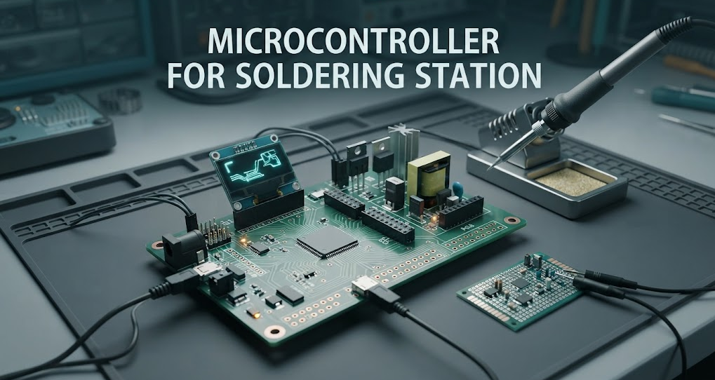
How to Choose a Microcontroller for a Soldering Station?
To choose a microcontroller for a soldering station, start with the sensor, heater, power stage, and required protections. Then match ADC behavior, timer/PWM resources, control-loop timing, memory, watchdogs, interfaces, and firmware support to that architecture. A larger or faster MCU is not automatically better; the right choice is the smallest controller that can be verified safely under the real thermal load.Commercial disclosure: QUICKO publishes this educational guide and sells soldering equipment and accessories. QUICKO links are commercial references. This article does not claim that any QUICKO station uses a particular MCU, firmware, sensor, heater, or control algorithm.
Quick Navigation
- Define the station architecture
- Set pass/fail requirements
- Match the sensor and ADC path
- Compare MCU classes
- Review control, protection, and firmware
- Validate the complete station
- Use the selection checklist
Start With the Control Architecture
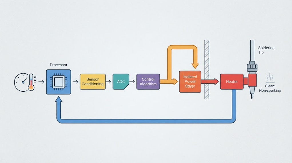
A soldering station has a target, sensor, signal-conditioning path, controller, power stage, heater, and tip or cartridge. The MCU sits inside that loop; it cannot compensate for a weak sensor, undersized power stage, poor grounding, or unstable heater interface.Write the architecture before opening a catalog: sensor family and signal range, heater voltage and current class, switching method, interface needs, calibration, fault states, and control-board isolation. A learning prototype, repairable bench tool, and repeatable product require different evidence.
A useful first rule is simple: if you cannot explain how a temperature change becomes a safe heater command and how an over-temperature event removes that command, the MCU selection is premature.
Apply Pass/Fail Gates Before Comparing Features
Use gates to remove unsuitable controllers before scoring performance or cost.| Gate | Evidence to request or design | Why it matters |
|---|---|---|
| Sensor path | Sensor type, range, conditioning, reference, filtering, and calibration method | The MCU must measure the real signal, not an assumed one |
| Heater and power stage | Supply, current class, switching device, isolation, gate-drive needs, and fault response | A capable MCU cannot make an unsafe power stage safe |
| Timing and control | Sampling interval, PWM or phase-control method, loop timing, and update behavior | Thermal control depends on predictable timing |
| Protection | Watchdog, brownout behavior, sensor-open detection, over-temperature path, and safe-off state | Fault handling must not depend on a frozen or confused firmware loop |
| Lifecycle | Toolchain, documentation, debug access, part availability, and firmware ownership | A station is maintained after the prototype works |
If a gate is undocumented, mark it unresolved. Do not choose by pin count, clock speed, or online popularity alone.
Match the Temperature Sensor to the Measurement Path
The sensor determines what the MCU can know. A thermocouple, RTD, thermistor, or cartridge-integrated sensor has different signal levels, linearity, bias, wiring, protection, and conditioning needs. Some signals need amplification or cold-junction compensation; others need a bias network or a dedicated converter. Do not assume that an MCU ADC can connect directly to every sensor.Nominal ADC resolution is only one part of measurement quality. Reference stability, noise, grounding, amplifier offset, sampling impedance, filtering, layout, and calibration also matter. The Analog Devices ADC accuracy tutorial explains why nominal bits and real accuracy differ.
Create a measurement budget before choosing the MCU: temperature range, acceptable error, sensor bias, sample interval, filtering delay, and calibration points. A suitable external converter may make a modest MCU adequate; direct measurement of a small noisy signal makes reference and analog performance more important.
Choose the MCU Class That Fits the Job
| MCU class | Often suitable for | Questions to resolve | Main trade-off |
|---|---|---|---|
| Basic 8-bit MCU | Simple single-channel control, small display, low-cost learning projects | ADC reference, timers, watchdog, memory, and toolchain support | Simple and accessible, but limited headroom and logging |
| 32-bit general-purpose MCU | Display, USB/UART logging, multiple sensors, richer UI, or future expansion | Real-time behavior, ADC performance, debug tools, library quality, and boot process | More capability, but more firmware and power complexity |
| MCU with strong analog peripherals | Designs needing comparators, synchronized ADC/PWM, or fast fault response | Peripheral interaction, errata, calibration, and isolation strategy | Can simplify control hardware, but requires deeper device expertise |
| MCU plus external ADC or controller | Small sensor signals, specialized converters, or a modular architecture | Interface latency, conversion faults, synchronization, and fail-safe behavior | Better measurement modularity, but more parts and failure points |
| Wireless-capable MCU | Connected logging or remote status is genuinely required | Security updates, radio coexistence, power behavior, and service policy | Adds connectivity options and additional attack and maintenance surface |
The best class is the one that leaves enough timing and memory margin for the required control and fault paths. Do not add wireless or a complex display just because the chip includes it. Every enabled feature creates firmware, testing, and support work.
Review PWM, Timers, and Control-Loop Timing
Thermal systems change slowly, but timing still must be deterministic. Define sensor sampling, control calculation, heater updates, and fault preemption. The Microchip PID application note provides general closed-loop terminology and tuning context.A proportional-integral-derivative controller is one possible approach, but it is not mandatory and its constants cannot be copied safely from another heater, tip, supply, or sensor. On-off, proportional, feed-forward, and hybrid methods may fit different thermal behaviors. The MCU must support the selected method with enough timing margin and observability to tune it.
Prefer hardware timers and hardware-enforced safe states where available. A watchdog should recover from a stalled firmware path, but it should not be the only over-temperature defense. The power stage needs an independent way to stop heating when the design risk requires it.
Check Protection and Serviceability
Define responses for sensor-open, shorted, disconnected, out-of-range, and implausibly fast readings, plus startup, brownout, watchdog, communication, button, and display faults. The safe result can vary by architecture, but it must be deliberate, testable, and documented.Separate normal control from fault handling. Log shutdown reasons where practical, but do not keep heating while waiting for a UI message. Version calibration constants and document the firmware, sensor map, connector pinout, and board revision for service.
Use the QUICKO Products page to understand current equipment categories, then request the exact manual or service information before assuming that a DIY controller can replace a commercial handle, cartridge, or station.

Validate the Complete Station, Not the MCU Datasheet
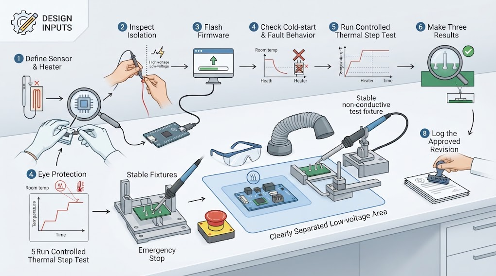
- Freeze the architecture: sensor, conditioning, MCU, firmware revision, power stage, heater, tip or cartridge, supply, and enclosure.
- Test cold start, normal setpoint changes, sensor disconnect, sensor short or out-of-range input, brownout recovery, watchdog recovery, and communication loss where applicable.
- Observe temperature measurement, heater command, overshoot, recovery, fault indication, and safe-off behavior with calibrated instruments and a defined test setup.
- Repeat the test after firmware, sensor, heater, power-stage, or calibration changes. A new revision is a new configuration.
- Make three representative joints using the intended solder, flux, tip, and workpiece. Record wetting, dwell, recovery, joint appearance, and nearby material condition.
- Quarantine any configuration that heats uncontrollably, loses sensor recognition, fails to enter a safe state, or cannot reproduce its recorded behavior.
- Retain the schematic, firmware build, calibration record, test conditions, and approval decision with the station.
Common Selection Mistakes
Choosing the most powerful or fastest MCU
Extra clock speed cannot compensate for poor sensor conditioning, noisy layout, weak power switching, or an undefined fault path.Treating ADC bits as temperature accuracy
Resolution does not include reference error, noise, offset, drift, sensor tolerance, or calibration. Build the measurement budget first.Copying PID values from another station
A different heater, tip, sensor, supply, or mechanical assembly changes the thermal response. Tune and validate the actual configuration.Making firmware the only safety layer
A stalled task, damaged input, or failed component can defeat a software-only assumption. Use deliberate hardware and system-level protections.Ignoring lifecycle and toolchain support
A controller that is easy to buy today may be difficult to program, debug, document, or replace later. Confirm the toolchain and revision path before standardizing.Selection Checklist
- [ ] Sensor type, range, conditioning, reference, and calibration method are documented.
- [ ] Heater, switching device, supply, isolation, and safe-off path are documented.
- [ ] ADC, timer, PWM, communication, memory, and watchdog needs are mapped.
- [ ] Startup, brownout, sensor fault, over-temperature, watchdog, and communication-loss behavior are defined.
- [ ] Firmware toolchain, debugger, boot process, versioning, and source ownership are clear.
- [ ] Three representative joints pass the project's predeclared criteria.
- [ ] The exact sensor, MCU, firmware, power stage, heater, tip, and supply revision is recorded.
- [ ] Service access, replacement parts, calibration, and documentation are available.
- [ ] A named technical reviewer has checked the safety and control assumptions.
FAQ
What is the best microcontroller for a soldering station?
There is no universal best MCU. Choose the smallest supported device that meets the sensor interface, timing, PWM, memory, communication, protection, debug, and lifecycle requirements with measurable margin. The heater and sensor architecture usually constrain the decision more than the processor brand.Is an 8-bit MCU enough for a soldering station?
It can be enough for a simple single-channel station when the sensor path, timing, UI, fault handling, and memory fit the design. Verify ADC behavior, timer resources, watchdogs, brownout handling, and toolchain support. A 32-bit MCU may be justified by logging, richer UI, multiple channels, or expansion, not by marketing alone.Do I need a PID controller?
Not always. PID is one closed-loop method, and its constants depend on the actual heater, sensor, tip, supply, and mechanics. On-off, proportional, feed-forward, or hybrid control may be suitable in another design. Select the method from measured behavior and validate it on the final configuration.Can I connect a thermocouple directly to the MCU ADC?
Do not assume so. Thermocouples produce small signals and may need amplification, filtering, reference compensation, protection, and careful layout. Check the sensor range, conditioning circuit, common-mode limits, ADC reference, and calibration method before connecting any input.What protections should the controller have?
Define sensor-open and out-of-range handling, over-temperature response, safe startup, brownout recovery, watchdog recovery, and a hardware or system-level path to stop heating. The exact implementation depends on the heater and power stage. A user-interface warning alone is not a safe-off mechanism.Should I use a wireless MCU?
Only when connected logging or remote status is a real requirement. Wireless capability adds firmware, security, update, power, and service considerations. A wired or simpler MCU may be easier to validate and maintain for a local bench station.Can a DIY controller replace a commercial soldering station board?
Only after the complete sensor, heater, power stage, firmware, enclosure, calibration, and safety behavior have been verified as a system. Mechanical fit or a working display does not prove thermal control or electrical safety. Keep the commercial board and DIY controller as separate documented configurations until testing supports a change.Conclusion
The right microcontroller for a soldering station is chosen from the control loop, not from a processor comparison chart. Map the sensor, ADC path, timers, PWM, power stage, fault handling, firmware lifecycle, and service plan before ordering parts. Then validate the complete configuration with fault tests and representative joints.QUICKO product pages identify station and accessory categories, while the QUICKO News hub provides related articles. Model-specific controller claims require current documentation and qualified review; do not call a DIY controller production-ready until measurements, safe-off behavior, thermal response, firmware revision, and maintenance are documented.


Linkedin:


