
 Tel:+86-13713635953
 Email:support@quicko.com.cn


How to Choose C245 Tips for Connectors and Ground Planes?
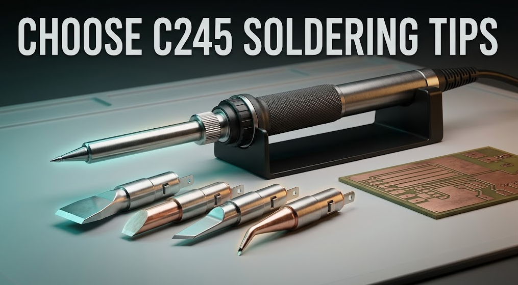
How to Choose C245 Tips for Connectors and Ground Planes?
To choose C245 soldering tips for connectors and ground planes, match the largest safe wetted face to the joint’s copper mass and clearance. Start with a broad chisel for flat tabs and ground-connected pads, use a bevel or hoof when a controlled solder bead or drag pass is useful, and select bent or knife shapes when access—not raw size—controls the approach. Confirm the exact cartridge and handle documentation before energizing.Commercial disclosure: QUICKO publishes this guide and sells soldering stations, handles, cartridges, tips, and accessories. QUICKO links are commercial references. This article does not claim universal C245 interchangeability or add unverified QUICKO wattage, dimensions, pinout, sensor, plating, recovery, or compatibility data.
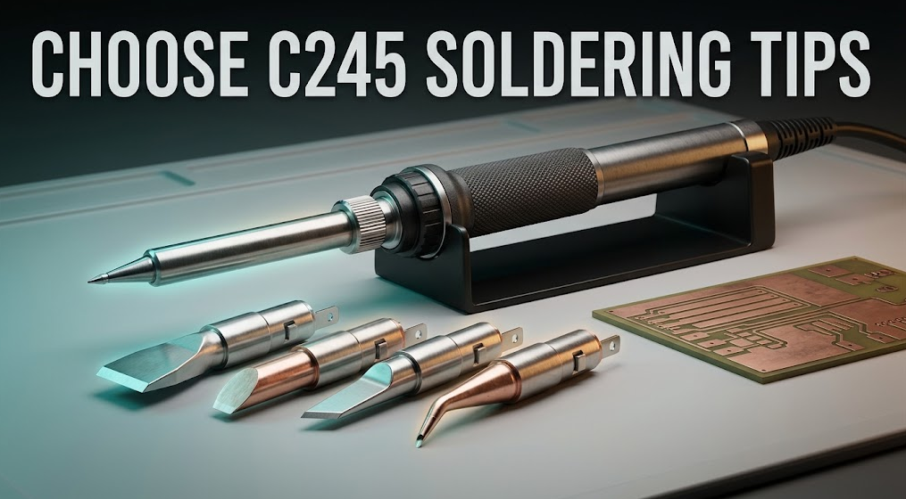
Direct Recommendation: Which C245 Shape Should You Start With?
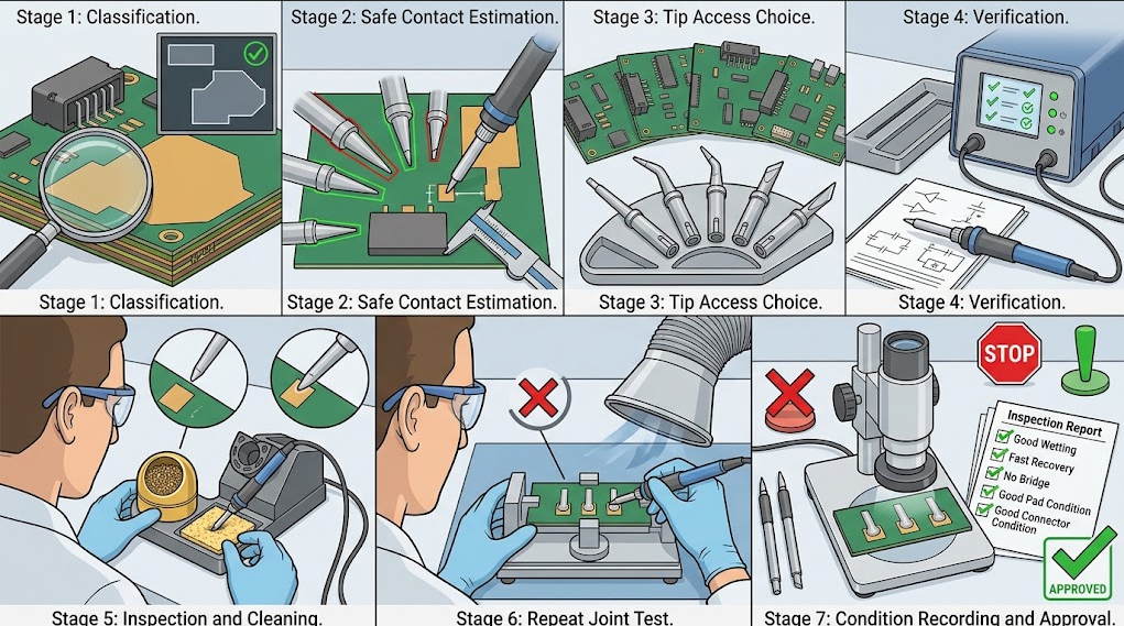
For most high-thermal-mass connector and ground-plane work, begin with a broad chisel whose flat face can contact the pad and terminal together. The flat face spreads heat into the joint more predictably than a point. Keep a bevel or hoof for controlled solder delivery and drag work, a bent chisel for microscope visibility around shields, and a knife edge for long pads or restricted side access.Use this seven-step decision sequence:
- Classify the joint. Note connector tab, through-hole pin, shield, ground pour, thermal via field, or large copper trace.
- Map clearance. Measure the nearest plastic, connector body, neighboring pad, and exposed conductor under magnification.
- Choose the contact face. Select the broadest face that touches the intended surfaces without bridging or scraping adjacent metal.
- Estimate heat load. A ground plane or heavy tab can pull heat away faster than an isolated pad; plan for contact efficiency, not just a higher setpoint.
- Choose the approach angle. Straight, bent, side, and knife geometries change visibility, reach, and the risk of lateral force.
- Verify the system. Match station, handle, cartridge family, controller, insertion depth, contacts, and supplier manual.
- Validate on a coupon. Accept the choice only after three repeat joints meet wetting, dwell, recovery, bridge, and substrate-protection criteria.
Why Connectors and Ground Planes Need More Than a Sharp Point
A connector tab or ground-connected pad can conduct heat into a large metal path. A sharp tip may reach the solder, but the small contact patch can deliver heat slowly and inconsistently. The operator then tends to press harder, hold longer, or raise temperature. Those compensations increase the chance of softened connector plastic, lifted pads, exhausted flux, oxidized plating, and laminate damage.A broad chisel creates a stable flat contact between tip, solder, terminal, and pad. A bevel or hoof adds a wettable angled face that can carry a controlled solder bead. A knife edge can transfer heat along a narrow pad or reach beside a shield, but it demands a steady angle. The right question is not “What is the biggest C245 tip?” It is “What is the biggest face that stays inside the safe clearance envelope?”
Use flux appropriate to the process, allow the solder to melt before moving the terminal, and keep the tip force light. Never lever against a connector body or drag across mask to compensate for a poor shape. If a ground joint still stalls, investigate pad geometry, board preheat, cartridge seating, supply behavior, and workholding before adding temperature.
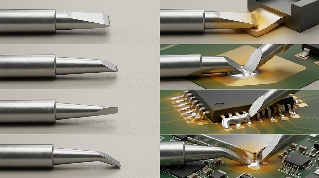
C245 Cartridge Tip-Shape Comparison
| Shape | Contact and solder behavior | Best-fit C245 tasks | Main limitation | Acceptance check |
|---|---|---|---|---|
| Broad chisel | Large, stable flat contact and high usable thermal mass | Connector tabs, ground pads, heavy traces, through-hole terminals | Can touch adjacent metal or plastic if oversized | Face fits the copper envelope and wets without connector deformation |
| Medium chisel | Predictable face with more clearance than a broad chisel | Medium tabs, shield seams, repeated high-load joints | May be slow on very large copper | Three joints recover consistently without excessive dwell |
| Bevel or hoof | Angled wettable face carries a controlled solder bead | Drag soldering, tab tinning, solder transfer | Excess bead can bridge or obscure the joint | Bead remains controlled and neighboring conductors stay separate |
| Knife edge | Narrow elongated contact reaches along an edge or pad | Long connector lands, shield-side access, selective drag | Angle-sensitive; can scrape mask or bridge if twisted | Edge stays stable and produces an even fillet |
| Bent chisel | Flat face with offset approach improves sight line | Dense connector rows, microscope work beside shields | Bend can encourage side pressure or uneven contact | Operator sees the face and reaches the joint without levering |
| Specialty/formed | Geometry follows a defined terminal or access constraint | Repetitive production joints or unusual connector cavities | Replacement and compatibility are more model-specific | Drawing, code, and coupon result all match the process |
Shape names vary by supplier. Compare the actual drawing, face width, angle, reach, and intended application rather than relying on “large,” “hoof,” or “power” in a marketplace title. The JBC C245 cartridge catalog should be read together with the exact handle and station documentation.
Key Specifications for Connectors and Ground Planes
Contact-face width and thickness
Record the usable flat, bevel, or edge—not only the outer barrel diameter. Width controls whether the face can contact both soldered surfaces while staying clear of adjacent conductors. Thickness and radius influence access to recessed tabs and the volume of solder the face can carry.Thermal mass and copper path
Describe the joint’s copper area, plane connection, thermal vias, terminal mass, and repetition rate. A tip that succeeds on an isolated pad may not recover fast enough on a ground plane. Use a larger safe face or board preheat where the process allows it; do not assume a temperature increase fixes poor coupling.Reach, angle, and visibility
Measure the distance from the working face to the connector body, shield, or microscope obstruction. Bent or knife shapes can keep the handle out of the viewing path. The best geometry permits a relaxed wrist and a light downward touch; if the tool must be twisted or pushed sideways, change the approach.Plating and wetting condition
A de-wetted or pitted face behaves like a smaller tip. Clean and tin according to the supplier’s approved method. Do not file, sand, or reshape plated C245 cartridges. Quarantine a face with exposed base metal, cracks, loose parts, unstable wetting, or abnormal discoloration.Cartridge-system compatibility
Confirm station model, handle, cartridge family, physical keying, insertion depth, contact arrangement, sensor behavior, controller support, supply, and firmware assumptions. Similar labels or a cartridge that slides into a socket do not prove safe electrical or thermal compatibility. Review the current QUICKO soldering products and C245-related categories and request the exact manual or compatibility statement before ordering a bulk pack.
Application Examples
Connector tabs and power terminals
Use a broad or medium chisel when the face can sit on the tab and pad together. Add flux, stabilize the connector, and protect nearby plastic. A bevel may help tin a broad surface or carry a small bead, but inspect for solder spreading into the housing. Acceptance means complete wetting, a smooth fillet, no void-like gaps visible at the edge, and no softened or displaced plastic.Ground planes and thermal pads
Choose the largest face that stays inside the exposed copper. A broad chisel reduces contact resistance and spreads heat, while a bevel can help introduce solder at an edge. If the joint remains cold, check plane connection, vias, preheat, flux activity, seating, and supply rather than repeatedly increasing temperature. Stop if mask blisters, pad edges move, or the board discolors.Shield seams and dense connector rows
Use a bent chisel or knife edge when straight access blocks the microscope view. Keep the working face aligned with the seam or terminal and avoid scraping the shield or mask. A narrow face is acceptable only when it still transfers enough heat; validate recovery and wetting on a representative coupon.Through-hole terminals on multilayer boards
The visible annulus may be smaller than the internal copper path. Use a medium or broad chisel with a stable rest, apply flux, and heat the terminal and pad together. Do not pull the lead while solder is partly molten. If the hole will not fill, inspect thermal load and solder volume before changing tip shape again.Consumables, Compatibility, and Procurement Checklist
Treat “C245” as a family label that still requires model-level verification. Before purchase, request the cartridge code, drawing, compatible handle list, controller requirements, electrical contact definition, storage and cleaning guidance, lot identification, warranty, and replacement policy. For third-party cartridges, ask the supplier to identify the exact station/controller combination rather than relying on a product-title match.Maintain a small validated set: one broad chisel for tabs and planes, one medium chisel for clearance-sensitive joints, and one bevel or bent shape for drag or restricted access. Store tips tinned, use sleep or hibernation functions when supported, and keep a clean, stable stand. The QUICKO soldering FAQ can help with general care questions, but the exact station and cartridge manual controls any model-specific procedure.
Controlled Validation and Acceptance Criteria
Use a scrap board or process coupon that matches the connector, copper plane, solder alloy, flux, and workholding of the intended job. The iFixit soldering guide provides general safety and technique context; it does not replace a documented C245 compatibility test.- Record station, handle, cartridge code, shape, supply, setpoint, solder, flux, board stack-up, copper connection, and ambient condition.
- Inspect the cold face, contacts, plating, insertion, and handle socket; confirm stable recognition.
- Make three repeat joints on the same connector or ground-plane geometry with the same operator sequence.
- Record time to wet, dwell, recovery between joints, visibility, hand angle, solder spread, and connector temperature or deformation observations.
- Inspect magnified fillets, mask, pad edges, vias, shield surfaces, and neighboring conductors.
- Accept only when all three joints meet the same wetting, bridge, pad, connector, and repeatability criteria without excessive force or temperature.
- Stop for uncontrolled heating, abnormal handle temperature, damaged insulation, unstable recognition, repeated bridges, pad movement, smoke, odor, or softened connector material.
C245 Tip Selection Checklist
- Is the joint a connector tab, ground plane, shield, through-hole terminal, or heavy trace?
- What is the largest safe face that contacts the intended copper without touching plastic or adjacent metal?
- Does the tip need a flat face, solder reservoir, edge, or offset approach?
- Can the operator see the face under the microscope without twisting or levering?
- Does the geometry match copper mass, thermal vias, solder alloy, flux, and repetition rate?
- Is the exact cartridge documented for the station, handle, controller, supply, contacts, and firmware?
- Are drawing, code, lot identity, storage, cleaning, warranty, and replacement details available?
- Do three repeat coupon joints meet wetting, dwell, recovery, bridge, pad, mask, and connector criteria?
- Has a named technical reviewer checked any QUICKO-specific claim before publication?
Frequently Asked Questions
What is the best C245 tip for a ground plane?
Start with the largest chisel face that fits inside the exposed copper and remains clear of neighboring conductors. A broad face improves thermal coupling, but board geometry and connector clearance set the limit. Validate three repeat joints and address plane heat sinking or preheat before simply raising temperature.Should I use a bevel or hoof on connector tabs?
Use a bevel or hoof when carrying a controlled solder bead or sweeping across a tab is useful. It can improve solder delivery, but excess solder may spread into a housing or bridge adjacent metal. Match bead size to the joint and inspect the connector after each trial.Is a larger C245 tip always faster?
No. A larger face can transfer more heat only when it fits the joint and remains well wetted. If it contacts plastic, mask, or an adjacent conductor, the extra size creates risk rather than speed. Choose the largest safe face and confirm recovery on the actual copper load.Does every C245 cartridge fit every C245 soldering station?
Do not assume so. Cartridge families can differ in keying, insertion depth, contact assignment, sensor behavior, controller support, and calibration. Confirm the exact station, handle, cartridge code, and current manual before applying power, even when the cartridge appears to fit mechanically.Why does a ground-plane joint remain cold at the setpoint?
The setpoint is not the same as heat delivered to the joint. Check face size, wetting, seating, copper connection, thermal vias, flux activity, supply behavior, and board preheat. A point that barely touches the solder may under-couple; a larger safe chisel often works better than a hotter, smaller tip.Can I file a C245 tip to make a custom shape?
No. Filing or sanding removes protective plating and changes the thermal and wetting surface unpredictably. Use a documented formed cartridge or ask the supplier about a supported specialty shape. Quarantine a tip with exposed base metal, cracks, pitting, or unstable wetting.How should I compare C245 recommendations from Reddit?
The r/soldering C245 discussions are useful for finding recurring operator questions about planes, connectors, and tip access. Treat them as anecdotal. Verify every dimension, compatibility, electrical, and safety claim against the current manufacturer documentation and your own coupon test.Conclusion
The practical way to choose C245 soldering tips is to match contact face, thermal load, access, and clearance to the connector or ground-plane joint. Start with a broad chisel for flat tabs and heavy copper, then add medium chisel, bevel, bent, or knife geometries when the application needs different solder-carrying behavior or visibility.Verify the complete station-and-cartridge system and run three repeat coupon joints before production. A good choice wets promptly, recovers consistently, avoids bridges and pad movement, protects connector plastic, and remains controllable without excessive force or temperature. Visit the latest QUICKO technical articles for related process guidance as product documentation and first-party test evidence expand.


Linkedin:


