
 Tel:+86-13713635953
 Email:support@quicko.com.cn


How Does PID Control Reduce Soldering Station Overshoot?
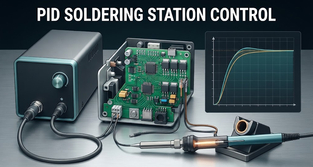
How Does PID Control Reduce Soldering Station Overshoot?
PID soldering station control reduces overshoot by adjusting heater power from the present temperature error, accumulated error, and the rate at which the error changes. Proportional action reacts to distance from the setpoint, integral action corrects persistent offset, and derivative action anticipates the trend. Overshoot is reduced only when those terms are tuned for the actual heater, sensor, tip, power stage, sampling interval, and workload; PID values cannot be copied safely from another station.Commercial disclosure: QUICKO publishes this educational guide and sells soldering equipment and accessories. QUICKO links are commercial references. This article does not claim that any QUICKO station uses a particular PID algorithm, coefficient, sensor, temperature, response time, or safety implementation without current documentation and configuration-specific testing.
Quick Navigation
- Define overshoot and the thermal system
- Understand proportional, integral, and derivative action
- See why sampling and power limits matter
- Prevent integral windup and noisy derivative action
- Tune with controlled steps and real loads
- Check faults and safe-off behavior
- Avoid common PID interpretation mistakes
What "Overshoot" Means in a Soldering Station
Overshoot is the amount by which the measured or working-surface temperature rises above the target after a setpoint change or thermal disturbance. A display may show one curve while the tip surface, sensor junction, or solder joint experiences another. Define which temperature matters before judging the controller.| Term | Meaning | Evidence needed |
|---|---|---|
| Setpoint | Requested target value | Controller setting and units |
| Measured temperature | Signal used by the loop | Sensor location, calibration, filtering, and sampling |
| Overshoot | Peak above target after a defined event | Starting state, event, endpoint, and logger |
| Settling | Time until response stays within a chosen band | Band definition, load, and repeatability |
| Recovery | Response after a joint removes heat | Joint geometry, tip, solder, dwell, and instrument |
The same station can show different overshoot under cold start, a small pad, a ground plane, or a large connector. A meaningful claim includes the event, sensor, load, and acceptance band.
The Three PID Terms
The Microchip PID control application note describes feedback: the controller compares a target with a measured value and changes its output. In a thermal system, the error is commonly the difference between target and measured temperature.Proportional action
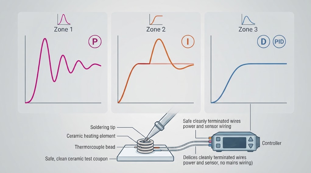
Proportional action increases heater command when error is large and reduces it as temperature approaches target. Too little can feel slow or leave offset. Too much can drive a large command near the setpoint and create oscillation or overshoot, especially when the sensor lags behind the working surface.Integral action
Integral action accumulates error over time and can correct a steady offset caused by heat loss or sensor bias. If the heater is already saturated while measured temperature remains below target, the integral term can keep accumulating. When temperature catches up, stored error can push the heater too hard. This is integral windup.Derivative action
Derivative action responds to the rate of change of error. It can reduce overshoot by backing off when temperature rises quickly. It is also sensitive to measurement noise, quantization, cable movement, and filtering delay. Practical implementations often filter or limit derivative action.
Why the Thermal Plant Changes the Result
PID controls a physical heater, sensor, tip, handle, supply, and workpiece. Thermal mass, heater-to-tip distance, sensor placement, air flow, board copper, joint size, and enclosure heat loss affect how temperature changes.The NI temperature-control tutorial is educational context for thermal tuning, but it does not provide coefficients for an untested soldering station. Treat every change to heater, sensor, tip, power stage, firmware sampling, or calibration as a possible change to the controlled plant.
Sampling, Saturation, and Anti-Windup
The controller acts on samples, not continuous temperature. A slow interval can miss a rapid rise; an overly fast loop can amplify noise. Filtering adds delay, while display smoothing can hide the actual control signal.Power saturation is another boundary. A station cannot command more heater power than its supply, switching device, connector, and firmware limit allow. When output is clamped, the integral term needs a deliberate anti-windup rule: stop integrating, back-calculate excess, or use another bounded strategy selected by the design team. The exact method is implementation-specific and must be tested.
How to Tune PID Without Chasing One Attractive Trace
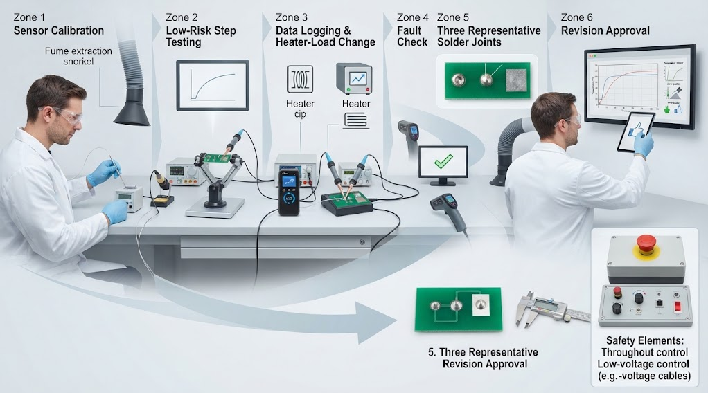
- Freeze the station, handle, tip or cartridge, supply, firmware, sensor calibration, solder, flux, coupon, and instrument.
- Define target, starting temperature, step size, allowed band, sampling interval, and logged signal.
- Begin with conservative limits and a low-risk load. Verify sensor disconnect and out-of-range states remove heater command as designed.
- Observe a proportional-only or otherwise bounded response to understand thermal lag before adding integral action.
- Add enough integral action to remove repeatable offset, then check for windup during startup and loaded recovery.
- Add derivative cautiously if the measured signal is stable; filter or limit noise rather than hiding it in a large coefficient.
- Repeat with a representative joint. Record peak, settling, recovery, joint quality, and nearby-material condition.
- Approve the complete configuration only after repeating results across the intended operating range and revisions.
Check Faults and Safe-Off Behavior
Define what happens when the sensor opens, shorts, disconnects, reports an implausible jump, or loses calibration. Also define startup, brownout, watchdog, communication, display, and button fault behavior. A controller should not continue heating while waiting for an error message.The OSHA electrical safety guidance provides general boundaries for energized equipment. It is not certification. For QUICKO equipment categories, start with the QUICKO Products page and request the exact manual, wiring information, and service record before discussing model-specific PID behavior.
Common PID Mistakes
Copying coefficients from another station
Different heaters, sensors, tips, supplies, and loads produce different dynamics. Copied coefficients can be unstable, slow, or misleading.Tuning from a display trace only
The display may be filtered or located away from the working surface. Log the relevant temperature and state the measurement method.Ignoring output saturation
If the heater is at its limit, the loop cannot respond as a mathematical model assumes. Tune with the real power boundary and anti-windup behavior.Increasing derivative to hide a sensor problem
Noisy or delayed sensing should be diagnosed in the measurement path. Large derivative action can make output chatter and obscure the cause.Testing only in free air
The joint removes heat. Use a defined coupon and representative task before judging process behavior.Selection and Validation Checklist
- [ ] Setpoint, measured signal, sensor location, calibration, and units are documented.
- [ ] Heater, tip or cartridge, supply, switching stage, output limit, and thermal load are identified.
- [ ] Sampling interval, filtering, control method, and derivative treatment are recorded.
- [ ] Overshoot, settling, and recovery events have defined endpoints and bands.
- [ ] Anti-windup behavior during heater saturation is understood and tested.
- [ ] Sensor-open, out-of-range, brownout, watchdog, and communication faults enter a deliberate safe state.
- [ ] Tests include cold start and at least three representative solder joints.
- [ ] Results are repeated after firmware, tip, sensor, heater, power, or calibration revisions.
- [ ] A named technical reviewer has checked control and electrical-safety assumptions.
FAQ
Does PID always eliminate soldering station overshoot?
No. PID can reduce overshoot when sensor, heater, sampling, output limits, and tuning match the thermal system. Sensor delay, excessive power, poor calibration, integral windup, noise, or an unrepresentative load can still produce a poor response. Validate the complete configuration instead of treating PID as a guarantee.Which PID term reduces overshoot most?
There is no universal answer. Proportional action affects reaction strength, integral action removes offset but can wind up, and derivative action can anticipate a rising temperature but amplify noise. Overshoot is a system-tuning issue involving terms, sensing, limits, and the actual soldering load.Why does a soldering station overshoot after reaching the setpoint?
Stored heat in the heater and tip can continue moving toward the working surface after the sensor approaches target. Sensor distance, filtering delay, aggressive proportional or integral action, output saturation, and thermal mass can contribute. Compare sensor and working-surface response under a defined test.Should I use derivative control on a soldering station?
Only when the measured signal is stable enough and the implementation can filter or limit noise. Derivative action may improve damping, but it can also react to quantization or sensor artifacts. Test it with the real sample interval, filter, heater, tip, and representative joint.Can I copy PID values from another soldering station?
Do not assume that is safe. Heater resistance, sensor location, tip mass, supply, power stage, firmware timing, and load change the plant. Use another station's values only as a documented starting hypothesis, then retune and validate the exact configuration.What should be logged during PID tuning?
Log setpoint, sensor temperature, heater command or duty, output saturation, sampling interval, filter state, ambient condition, tip or cartridge, load, and firmware revision. Also record overshoot, settling, recovery, joint quality, and fault behavior.Conclusion
PID soldering station control reduces overshoot by combining present error, accumulated error, and temperature trend, but it works only inside a measured thermal system. Define the sensor and endpoint, respect power saturation, prevent integral windup, handle noisy derivative signals, and validate cold start, loaded recovery, faults, and real solder joints. Treat every heater, tip, sensor, firmware, and calibration change as a new configuration.QUICKO product and support pages can organize further station research, while model-specific PID behavior, coefficients, temperature, recovery, and safety claims require current documentation, qualified review, and configuration-specific test records.


Linkedin:


