
 Tel:+86-13713635953
 Email:support@quicko.com.cn


How Does a Soldering Iron Heat Up Through Its Heater, Sensor, and Tip?
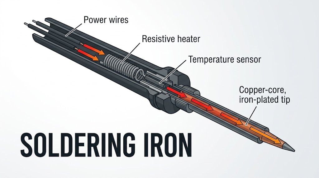
How Does a Soldering Iron Heat Up Through Its Heater, Sensor, and Tip?
A soldering iron heats up by passing electric current through a resistive heating element. Electrical resistance converts part of that energy into heat, the tip conducts the heat to the joint, and a temperature sensor tells the controller when to add or reduce power. The whole process is a controlled heat-transfer system, not simply a hot metal rod.This guide is for electronics hobbyists, repair technicians, production operators, and buyers who want to understand what happens between pressing the power switch and melting solder. It covers electrical heating, heat conduction, sensing, closed-loop control, and thermal recovery. It does not claim performance figures for a specific QUICKO model; always verify the actual station, handle, cartridge, power-supply, and tip specifications before use.
|
Commercial disclosure QUICKO publishes this technical guide and sells soldering stations, irons, handles, cartridges, and tips. Product-category links in this article lead to QUICKO pages; the cited physics and measurement references are independent external sources. |
Key Takeaways
· A resistive heater converts electrical power into heat through Joule heating.· Heat must travel through the heater, interfaces, tip body, wetted tip surface, and solder joint.
· The temperature sensor measures a point in that heat path, not necessarily the exact contact temperature at the joint.
· Closed-loop control repeatedly compares measured temperature with the setpoint and adjusts heater power.
· Wattage affects available heating rate and recovery, but tip geometry and thermal contact often matter just as much.
· A cartridge tip can reduce thermal lag by placing the heater and sensor closer to the working end.
Table of Contents
1. What converts electricity into heat?2. Where are the heater and sensor located?
3. How does heat travel to the solder joint?
4. How does closed-loop temperature control work?
5. Why does tip temperature drop during soldering?
6. How do power and resistance affect heating?
7. How can you diagnose slow heating or poor recovery?
8. How should you choose a soldering system?
What Converts Electricity into Heat in a Soldering Iron?
The heater is an electrical resistance designed to run hot. When voltage is applied, current flows through the heater and electrical energy is converted into thermal energy. This is commonly called Joule heating.The basic power relationships are:
P = V x I
P = I^2 x R
P = V^2 / R
Here, P is power in watts (W), V is voltage in volts (V), I is current in amperes (A), and R is resistance in ohms. The OpenStax explanation of electric power and energy provides the underlying electrical relationships.
Consider a simplified heater with a resistance of 8 ohms connected to 24 V:
· Current: I = 24 V / 8 ohms = 3 A
· Electrical power: P = 24 V x 3 A = 72 W
· Equivalent check: P = 24^2 / 8 = 72 W
If the same 8-ohm heater received only 12 V, the ideal electrical power would be 18 W, not 36 W. Halving voltage reduces power to one quarter when resistance is treated as constant. Real heater resistance can change with temperature, and the controller may pulse power rather than apply full voltage continuously, so this calculation is a design example rather than a product rating.
Where Are the Heater and Temperature Sensor Located?
Soldering irons use several mechanical arrangements, but two broad architectures explain most systems.Separate heater and removable tip
In a traditional arrangement, a ceramic or wire-wound heater sits inside the handle or heater tube. A separate metal tip fits over or around it. Heat crosses at least one mechanical interface before reaching the working end. Oxidation, looseness, contamination, and poor fit at that interface increase thermal resistance and slow heat transfer.Integrated cartridge tip
In a cartridge system, the heater, sensor, and tip are assembled into one replaceable unit. T12, C210, and C245 are examples of cartridge-based ecosystems represented in the QUICKO product range. Integration shortens the heat path and can reduce the lag between a temperature change at the working end and the controller's response. Actual compatibility is system-specific; a similar-looking cartridge should never be assumed compatible without checking its connector, heater, sensor, voltage, and control requirements.Commercial cartridge systems use the same design direction: move the heater and sensor closer to the working end and shorten the path through which heat and measurement signals must travel. JBC describes this approach in its overview of an efficient soldering heating system. The page is a manufacturer source, so this article uses it only as an example of cartridge-system architecture, not as independent proof of comparative performance.
The sensor may be a thermocouple, a resistance-based sensor, or another temperature-dependent element. A thermocouple generates a small voltage related to the temperature difference between its measurement junction and reference conditions. National Instruments explains the measurement principle and cold-junction compensation in its thermocouple measurement reference.
The most important design question is not merely whether a sensor exists. It is how far the sensor is from the working surface and how much thermal resistance lies between them. A sensor buried farther from the joint can report a stable temperature while the actual contact region has already cooled under load.
How Does Heat Travel from the Heater to the Solder Joint?
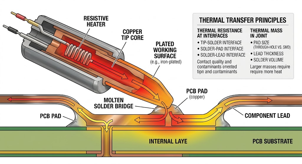
Heat moves mainly by conduction through the solid parts of the iron. The path can be modeled as a series of thermal resistances:Heater -> heater-to-tip interface -> tip body -> plated working surface -> solder bridge -> pad and component lead
The OpenStax overview of heat-transfer methods describes conduction as energy transfer through matter without bulk movement of that matter. In a soldering iron, a larger temperature difference can drive more heat through a given path, while a longer, thinner, or poorly contacting path resists heat flow.
Several practical details change the result:
· Tip material: Copper conducts heat well, while protective iron plating provides durability and a solder-wettable working surface. Other barrier and chrome-plated regions help control corrosion and where solder wets.
· Tip geometry: A broad chisel or bevel provides more contact area than a needle-like point when the joint is also broad.
· Interface fit: A loose removable tip can create an insulating air gap or reduced contact area.
· Wetted contact: A small amount of molten solder forms a thermal bridge that fills microscopic gaps between the tip and joint.
· Joint thermal mass: A large connector, thick wire, metal shield, or ground plane absorbs heat faster than a small isolated pad.
This explains a common mistake: turning the station to a much higher temperature while continuing to use a tip that contacts the joint at only one tiny point. A better-matched tip can transfer heat faster at a lower setpoint because it reduces contact resistance and increases the effective contact area.
How Does Closed-Loop Temperature Control Work?
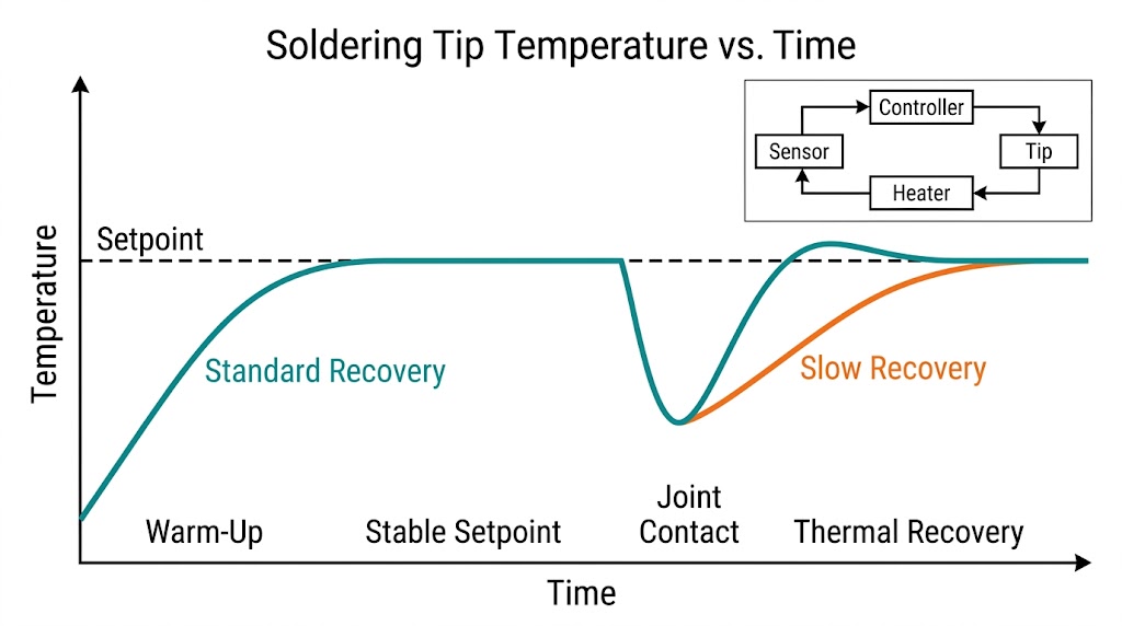
A temperature-controlled station operates as a feedback loop. The user selects a setpoint, the sensor reports a measured value, and the controller decides how much power to deliver to the heater.The control cycle is:
9. Read the sensor. The controller samples a thermocouple, resistance sensor, or integrated cartridge signal.
10. Compare with the setpoint. It calculates the temperature error: setpoint minus measured temperature.
11. Apply heater power. A switching device, often a transistor or MOSFET in low-voltage stations, controls current to the heater.
12. Measure again. The controller repeats the cycle and reduces power as the measured temperature approaches the target.
13. Respond to load. When the tip touches a joint and cools, the controller detects the change and increases power.
Simple controllers use on/off regulation or proportional control. More advanced systems may combine proportional, integral, and derivative terms, commonly called PID control. The exact algorithm matters, but it cannot overcome a poorly fitted tip, inadequate power supply, damaged heater, distant sensor, or undersized contact area.
The displayed number also needs context. It is the controller's interpretation of the sensor signal after calibration. It is not a guarantee that every point on every tip has exactly the displayed temperature, particularly while heat is flowing rapidly into a large joint.
Why Does the Tip Temperature Drop During Soldering?
The tip stores a finite amount of thermal energy. As soon as it touches a cooler joint, energy flows into the pad, lead, solder, and surrounding board. If heat leaves the tip faster than the heater can replace it, the working surface cools.Four variables largely determine recovery:
| Variable | What improves recovery | What weakens recovery |
| Available heater power | Adequate voltage, current capacity, and controller output | Undersized supply, cable loss, limited duty cycle |
| Thermal path | Integrated heater/sensor, tight interfaces, short path | Loose tip, contamination, long path, air gaps |
| Tip thermal capacity | Enough metal near the working end for the joint | Very small tip on a high-mass joint |
| Contact conductance | Tip face matched to the joint with a small solder bridge | Point contact, dry surface, oxidized tip |
Warm-up time and recovery time are related but not identical. An unloaded iron can reach its sensor setpoint quickly and still recover poorly on a large ground plane. A meaningful comparison should therefore include both no-load heat-up and temperature behavior under a defined thermal load.
How Do Power, Resistance, and Control Affect Heating?
Power is the rate at which electrical energy is delivered, but not all rated power reaches the joint. Some heat warms the handle-side structure and surrounding air. Some remains stored in the tip. The rest can flow into the workpiece when contact is made.Use this simplified worksheet when checking a low-voltage heater:
| Input | Symbol | Example |
| Supply voltage | V | 24 V |
| Measured cold resistance | R | 8 ohms |
| Calculated current | I = V / R | 3 A |
| Calculated ideal power | P = V^2 / R | 72 W |
| Minimum ideal supply capacity | V x I | 72 W |
Add engineering margin for the controller, display, conversion loss, transient demand, cable resistance, and supply temperature. Do not select a power supply from this single calculation alone. Confirm the controller's input range, heater rating, connector pinout, grounding, and protection requirements.
Why a higher setpoint is not the same as higher power
Temperature is a state; power is an energy-transfer rate. Raising the setpoint increases the temperature difference between the tip and joint, but it can also accelerate oxidation and increase the risk of pad or component damage. Increasing available controlled power can improve recovery without requiring an unnecessarily high idle temperature, provided the tip, cartridge, controller, and supply are designed for it.How Can You Diagnose Slow Heating or Poor Thermal Recovery?
Start with the heat path instead of immediately changing calibration.14. Confirm the symptom. Separate slow warm-up, low indicated temperature, low actual tip temperature, and rapid temperature drop under load.
15. Inspect the tip. Look for oxidation, a non-wetting surface, loose fit, deep wear, or the wrong geometry for the joint.
16. Check the solder bridge. A clean, tinned tip should create a small molten bridge to the work.
17. Verify the power source. Check the required voltage, current capacity, cable, connector, and supply behavior under load.
18. Measure heater resistance only under safe, specified conditions. Disconnect power first unless the service procedure explicitly requires a live measurement.
19. Check the sensor and wiring. Intermittent handle contacts can imitate heater or control faults.
20. Measure recovery with a repeatable load. Record tip type, setpoint, ambient conditions, contact time, load, and measurement method.
Do not file or grind a plated soldering tip to expose fresh copper. Removing protective plating can shorten tip life and change wetting behavior. Follow the cartridge or tip manufacturer's maintenance instructions, and replace a structurally damaged tip.
How Should You Choose a Soldering System?
Choose the system around the joints you need to heat, not around the highest temperature shown on a display.· For fine-pitch work, prioritize precise tip geometry, low moving mass, accessible cartridge shapes, and controlled response.
· For large ground planes, connectors, shields, and thick wires, prioritize contact area, available power, tip thermal capacity, and recovery under load.
· For mixed repair work, consider the range and cost of compatible tips, handle ergonomics, standby behavior, calibration workflow, grounding, and replacement availability.
· For DIY controllers, verify the heater/sensor electrical design, connector pinout, power-supply requirements, fault detection, grounding, and overtemperature behavior before connecting a cartridge.
QUICKO offers T12, C210, C245, cordless, and DIY soldering product categories. Browse the QUICKO soldering stations, irons, handles, and tips to identify the relevant system family, then confirm the exact product specifications before ordering. For further learning, use the QUICKO soldering guides and QUICKO soldering FAQs.
Frequently Asked Questions
How long does a soldering iron take to heat up?
Heat-up time depends on heater power, tip mass, thermal-path resistance, sensor position, controller behavior, starting temperature, and the selected setpoint. A no-load heat-up figure alone does not predict recovery on a real joint. Compare systems using the same tip, setpoint, starting conditions, and defined thermal load.Does a higher-wattage soldering iron get hotter?
Not necessarily. In a temperature-controlled system, wattage mainly indicates how quickly the heater can deliver energy and recover from a load within its control limits. The setpoint governs target temperature. A higher-power station can hold temperature better on demanding joints without requiring a higher idle temperature.Why is the sensor temperature different from the tip contact temperature?
The sensor measures its own location inside or near the heater assembly. Heat must still cross material and interface resistances before reaching the working surface. During heavy soldering, the contact region can cool faster than the sensor detects, especially when the sensor is farther from the tip end.Why do cartridge tips usually respond faster?
Cartridge tips place the heater, sensor, and tip body in one assembly, shortening the thermal and sensing paths. That can reduce lag and improve control response. Performance still depends on cartridge design, power supply, controller tuning, tip geometry, contact condition, and the joint's thermal mass.Can I measure soldering tip temperature with a standard thermocouple?
You can, but contact geometry, sensor type, bead size, wetting, pressure, calibration, and heat loss can produce large errors. A purpose-built soldering-tip thermometer offers a more repeatable contact arrangement. Record the method and conditions whenever comparing stations or checking calibration.Conclusion
A soldering iron is a compact feedback-controlled heat-transfer system. The heater converts electrical power into heat, the tip conducts and stores that heat, the solder bridge transfers it into the joint, and the sensor-controller loop replaces energy lost under load. Understanding that chain makes power, tip shape, cartridge design, calibration, and recovery easier to evaluate.The practical rule is simple: use the largest tip face that safely fits the joint, keep it clean and wetted, choose enough controlled power for the thermal load, and verify compatibility rather than relying on appearance. Explore QUICKO soldering products when you are ready to compare T12, C210, C245, cordless, or DIY station options.
Sources
21. OpenStax, College Physics 2e, "Electric Power and Energy", accessed August 15, 2026.22. OpenStax, College Physics 2e, "Heat Transfer Methods", accessed August 15, 2026.
23. National Instruments, "Thermocouples", accessed August 15, 2026.
24. JBC Soldering Tools, "The Most Efficient Soldering System", accessed August 15, 2026.
Publication Safety Note
Soldering tools operate at burn temperatures and may expose users to fumes, molten solder, energized circuits, or lead-containing materials. Use suitable ventilation, eye protection, heat-safe handling, and the applicable electrical and material-safety procedures. Disconnect power before resistance or continuity tests unless an authorized service procedure explicitly requires a live measurement.


Linkedin:


