
 Tel:+86-13713635953
 Email:support@quicko.com.cn


How Does USB-C Power Delivery Run a Portable Soldering Iron?
How Does USB-C Power Delivery Run a Portable Soldering Iron?
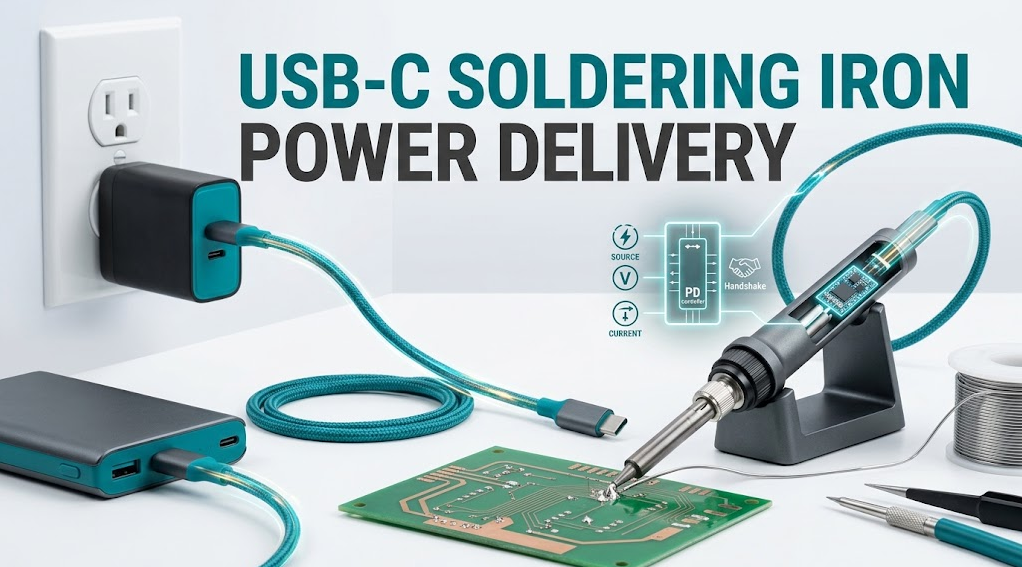
USB-C soldering iron power delivery is a system, not a connector. A portable iron can use USB-C as a physical interface while relying on USB Power Delivery negotiation to request a suitable voltage and current. The source, cable, sink controller, DC conversion stage, heater, sensor, and tip must all work together. If one part cannot sustain the requested power, the iron may still light its display while heating slowly, resetting, or losing temperature under a real joint.This guide explains the negotiation path in plain language, shows how to match a USB-C charger and cable, and provides a safe troubleshooting sequence. It is written for hobbyists, repair technicians, service teams, and B2B buyers. QUICKO product links are commercial references; verify the exact model manual before assuming USB-C support.
Commercial disclosure: QUICKO publishes this guide and sells portable soldering stations, irons, handles, cartridges, and tips. QUICKO does not claim that every QUICKO model or every USB-C accessory supports USB Power Delivery.
Quick Answer: How Does USB-C PD Power a Soldering Iron?
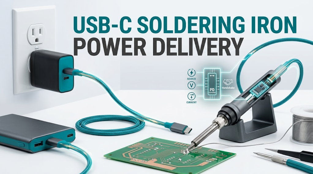
A USB-C Power Delivery soldering iron starts by identifying the source and sink, negotiating an available power contract, converting that input to the heater and controller's operating rails, and regulating heat through a sensor-feedback loop. The charger advertises capabilities; the iron requests a suitable profile; the cable must be rated for the negotiated current. A USB-C plug that fits proves only mechanical connection, not safe or sufficient power.USB-C, USB PD, and the Power Contract
USB-C describes a connector and cable ecosystem. USB Power Delivery is a protocol that allows a source and a powered device to communicate about available power. According to the USB Power Delivery specification overview, PD can provide flexible power over one cable, and the device can request power rather than accepting one fixed output.The practical sequence is:
1. Attach: the source and sink detect a USB-C connection.
2. Advertise: the source communicates one or more available power capabilities.
3. Request: the iron's sink policy asks for a supported contract.
4. Accept and apply: the source accepts, then the iron enables its input path and conversion stage.
5. Regulate: the controller allocates power between heater, sensor, display, and protection functions.
6. Adjust or stop: if demand or safety conditions change, the contract or output may be reduced or shut down.
USB PD 3.1 allows higher power levels, including up to 240 W, but only when the charger, cable, connector, and device all support the relevant requirements. That number is a protocol capability ceiling, not a recommended setting for a soldering iron.
The Complete Power Path Inside a Portable Iron
After negotiation, the input does not go directly to the tip. A portable iron typically has several functional blocks, although the exact design varies:· USB-C receptacle and protection: handles insertion, overcurrent, electrostatic, and transient risks.
· PD sink controller: interprets the source's capabilities and requests a profile.
· DC conversion and regulation: creates the rails needed by the controller, display, sensor, and heater.
· Power switch or current stage: meters heater energy and responds to limits.
· Sensor and control loop: compares measured tip behavior with the selected target.
· Heater and cartridge: converts electrical power into heat at the working tip.
· Mechanical and thermal path: transfers heat through the cartridge, tip plating, solder bridge, and joint.
The display may run from a low-power rail even when the heater path is current-limited. That is why “the screen is on” is not proof that the source, cable, and converter can sustain soldering power.

Why a Portable Iron Needs More Than a High-Watt Charger
A higher-rated charger cannot force a tool to accept more power than its sink controller and conversion stage request. Conversely, a powerful iron can be limited by a small charger, a shared power bank, a cable with lower capability, connector resistance, or thermal protection. The useful question is not “How many watts does the charger advertise?” but “What contract does this exact iron request, and can the entire path sustain it under load?”Average draw also changes during use. Heat-up can demand a high burst; an idle iron may draw little; a large copper pad can trigger recovery; and sleep mode can reduce demand until the tip wakes. Compare source behavior at idle and under a defined joint load rather than relying on no-load display readings.
How to Match a USB-C Charger to a Soldering Iron
Use the product manual as the source of truth. Build a compatibility record with these fields:| Field | What to verify | Why it matters |
|---|---|---|
| Iron input | Supported PD profiles, maximum input, fallback behavior | Determines what the sink can request |
| Charger or power bank | Advertised profiles and sustained output | A peak label may not describe continuous heater support |
| Cable | Current/power marking, e-marker if required, condition, length | Cable capability and resistance affect the contract and voltage at the tool |
| Shared loads | Other devices on the charger or power bank | Available power can fall when another device draws energy |
| Connector | Fit, retention, heat, discoloration, contamination | Poor contact increases resistance and can create a safety risk |
| Environment | Temperature, moisture, dust, movement | Field conditions affect cable and connector reliability |
Do not infer a voltage from a USB-C connector's shape, cable color, or a marketplace photograph. The USB Type-C cable and connector specification is the appropriate reference for the ecosystem; the iron's manual determines its actual supported input.
Cable Resistance, Voltage Drop, and Heat Loss
Every cable and connector has resistance. Under high current, the voltage drop is approximately:`voltage drop = current x resistance`
The cable's heat loss is approximately:
`power loss = current squared x resistance`
These are Calculated relationships, not a claim about a particular QUICKO setup. A longer, thinner, damaged, or poorly terminated cable can produce more drop and heat than a short, rated, undamaged cable. The iron may respond by limiting input, resetting, or delivering slower heat recovery.
Use the shortest practical cable that meets the manual and the field layout. Avoid coiling a high-current cable tightly while loaded, crushing it under a case, or repeatedly flexing the connector at the tool. If the plug or receptacle becomes unusually hot, smells unusual, changes color, or loses contact when moved, stop using the setup.
USB-C Soldering Iron Troubleshooting by Symptom
The display turns on, but the tip heats slowly
Check whether the charger negotiated the required profile, whether another device is sharing the source, and whether the cable is correctly rated and undamaged. Return to one approved charger and one approved cable. Then compare no-load heat-up with a defined soldering load. Do not compensate by guessing a higher temperature.The iron resets when the tip touches a joint
The joint may demand more recovery power than the source path can provide. Check the tip geometry, solder bridge, cable, connector, source current limit, and shared-load state. Record whether the reset happens only on a high-mass joint. Repeated resets are a stop condition until the exact manual and source requirements are checked.The cable or connector gets hot
Power loss from resistance can heat a cable or contact. Disconnect, allow the setup to cool, inspect for contamination or damage, and substitute only one known-good rated cable or charger. Do not continue to use a connector that is discolored, loose, cracked, or intermittently powered.A power bank works for the display but not the heater
The power bank may offer a low-power default, lack the requested PD profile, reduce output under shared load, or enter protection when heater demand rises. Confirm the iron's requirements and the power bank's sustained profile. A display-only success is not a valid heater test.The iron works with one charger but not another
The chargers may advertise different profiles, current limits, cable requirements, or fallback behavior. Record the exact source and cable pair. Do not assume that a larger printed wattage is more compatible; the sink must request a profile it supports.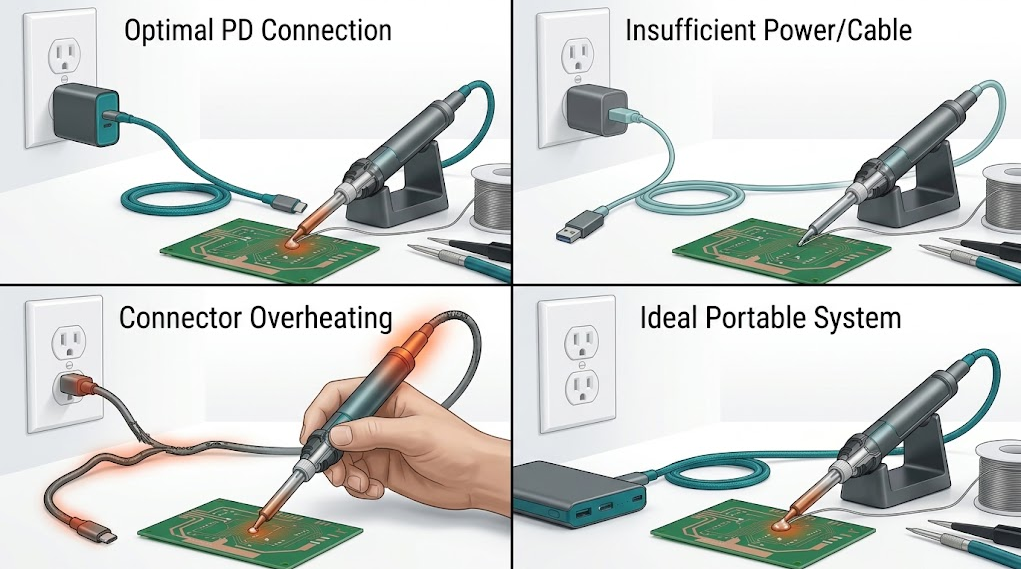
A Safe Diagnostic Sequence
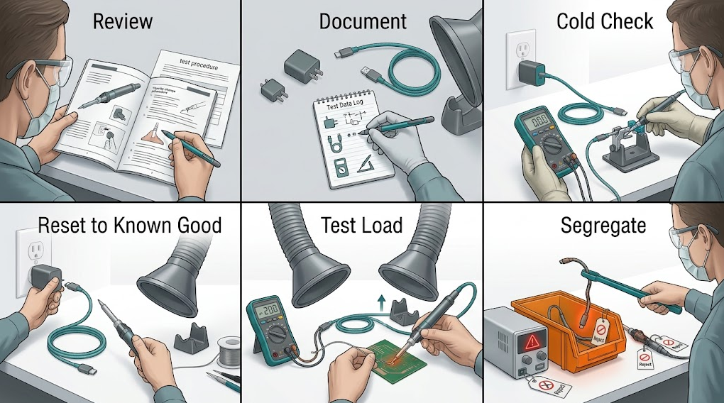
Use a controlled sequence instead of swapping multiple components:7. Record the symptom: model, firmware if relevant, charger, cable, power-bank state, profile, tip, joint, and timing.
8. Make it safe: stop heating, place the tip in its stand, disconnect the source, and let the tool and connector cool.
9. Inspect externally: look for damaged insulation, bent contacts, contamination, looseness, discoloration, or moisture.
10. Restore one approved configuration: use the exact documented charger and cable, with no hub or adapter unless approved.
11. Test idle and load: compare the display and heat behavior first in air, then on a representative joint with safe workholding.
12. Change one variable: substitute one known-good cable or source, not several parts at once.
13. Escalate: quarantine the setup if heat, resets, odor, exposed conductors, or uncontrolled temperature remains.
The iFixit soldering and desoldering guide emphasizes power isolation, stable workholding, eye protection, tip cleaning, and fume control. Those controls apply to a USB-C iron even though its heater source is portable.
Selecting Tips and Settings After Power Is Correct
Power delivery cannot fix every heat-transfer problem. A fine tip on a large copper plane may lose heat quickly even when the source is fully capable. Choose a tip face that safely fits the joint, keep it clean and wetted, use suitable flux and solder, and avoid increasing temperature blindly.QUICKO's T12 soldering tip range and black-finish T12 tip options are useful references for tip planning, but they are not proof of USB-C or handle compatibility. Confirm the iron's approved tip family, heater/cartridge arrangement, and controller limits first.
Safety Boundaries for USB-C Portable Soldering
Stop and isolate the setup when any of these conditions appears:· Hot, loose, cracked, wet, or discolored USB-C connector
· Damaged cable, exposed conductor, or repeated intermittent power
· Smoke, unusual odor, arcing, sparks, or uncontrolled heating
· Battery swelling, leakage, unusual heating, or physical damage
· Repeated source protection, resets, or fault messages under the same load
· Unknown adapter, modified wiring, open mains charger, or missing documentation
Never open a mains charger or bypass overcurrent, thermal, or battery protection to make a portable iron work. OSHA electrical-safety resources provide broad workplace guidance; they do not replace qualified service procedures or the product manual.
Field-Test Worksheet
Before standardizing a USB-C soldering iron, run a small documented pilot. Use the same charger, cable, tip, solder, flux, setpoint, workpiece, and inspection rule for each candidate. Record:
· Source model and advertised PD profiles
· Cable model, rating, length, and condition
· Iron model, firmware, tip, and requested profile
· Idle input behavior and defined-load behavior
· Heat-up and recovery observations, labeled Measured if timed with a stated method
· Resets, source protection, connector temperature observations, and anomalies
· Number and type of joints completed before the source or battery state changed
· Operator comfort, cable routing, stand stability, and pack-out time
Do not convert a short pilot into a universal runtime or safety claim. Report the exact configuration and workload.
QUICKO Product and Link Guidance
QUICKO's cordless soldering station catalog is a starting point for comparing portable station architectures. The current product page includes configuration-specific fields and may not represent a USB-C PD input. Request the exact manual and written input specification before connecting a USB-C charger.For general product discovery, use the QUICKO soldering product index and ask support to confirm whether a selected model is battery-powered, USB-C PD-powered, DC-input, or another architecture. Never infer input compatibility from a product photograph.
Frequently Asked Questions
Can any USB-C charger run a portable soldering iron?
No. The iron must support a compatible USB Power Delivery profile, and the charger, cable, connector, and power bank must sustain the requested current. Check the exact manual and source documentation together. A USB-C plug that fits can still deliver only a low-power fallback or reset under heater load.Does USB-C PD automatically provide 240 W?
No. USB PD 3.1 defines higher-power options for compatible equipment, but the actual contract is limited by the source, cable, sink controller, connector, and device design. Treat 240 W as an ecosystem capability ceiling, not as a default voltage or a safe target for an unknown soldering iron.Why does a USB-C iron heat in air but cool on a joint?
The joint may remove heat faster than the tip can replace it, or the source path may reach a current limit. Check tip geometry, solder bridge, flux, negotiated profile, cable condition, connector resistance, and shared loads. Test a defined joint with the exact approved configuration before changing temperature.Is a longer USB-C cable better for field work?
Only when its rating, construction, and routing meet the tool's requirements. Longer cable length can add resistance, voltage drop, and heat under high current. Use the shortest practical rated cable, keep connectors supported, and replace any cable that is damaged, hot, intermittent, or poorly retained.Should I use a USB-C hub or dock between the charger and iron?
Only if the soldering iron manual explicitly supports that path. Hubs and docks can negotiate differently, share power with other loads, or introduce extra resistance and protection behavior. For diagnosis, remove unapproved hubs and test one documented charger and cable directly.Can I replace the USB-C cable with any higher-wattage cable?
No. Confirm the cable's current capability, construction, connector quality, and the source and iron's negotiated profiles. A higher marketing number does not prove correct signaling, fit, or durability. Use a cable documented for the required USB-C PD contract and inspect it before every field session.Conclusion
USB-C Power Delivery runs a portable soldering iron through a negotiated power contract, a protected input path, conversion electronics, a heater-control loop, and the final tip-to-joint thermal path. The connector alone tells you almost nothing about the safe or useful operating point.For QUICKO buyers, the next step is to record the exact iron model, requested PD profile, charger, cable, tip, and representative joint. Test idle and load behavior with one approved configuration, then investigate any reset, hot connector, or unstable temperature before deployment.


Linkedin:


