
 Tel:+86-13713635953
 Email:support@quicko.com.cn


How to Calculate Cordless Soldering Iron Battery Runtime
How to Calculate Cordless Soldering Iron Battery Runtime
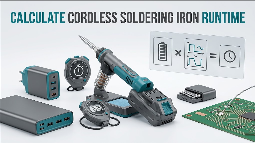
To calculate cordless soldering iron runtime, convert the source into usable watt-hours, estimate or measure average electrical power, and account for conversion losses and the tool's duty cycle. The basic relationship is simple, but the inputs are often misunderstood: a battery's nominal watt-hours are not all available at the tip, a heater's peak rating is not its average draw, and a long recovery on a copper plane can consume much more energy than a short signal joint.This tutorial gives you a transparent calculation, sensitivity examples, and a controlled field-test method. It is for hobbyists, technicians, service teams, production engineers, and B2B buyers comparing a battery station, internal-battery iron, USB-C soldering iron, or power-bank setup.
Quick Answer: What Is the Runtime Formula?
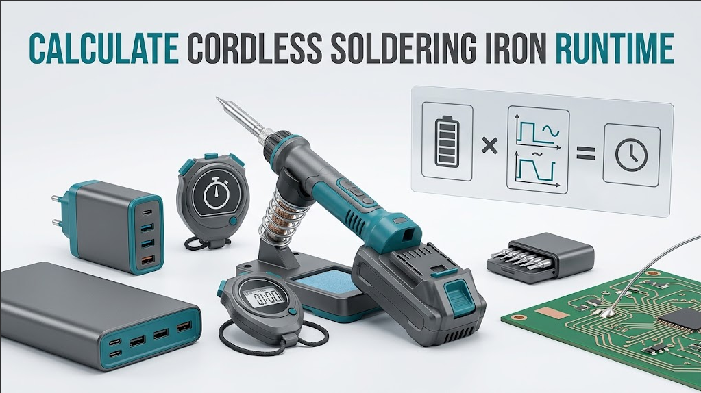
The planning formula is runtime equals usable battery watt-hours multiplied by system efficiency, divided by average electrical watts. First calculate nominal energy as volts multiplied by amp-hours. Then reduce it for reserve charge, conversion loss, battery condition, temperature, and protection limits. Finally use average power across heat-up, active soldering, recovery, and idle time. Label the result Calculated until a defined workload has been measured.Step 1: Convert Battery Labels to Watt-Hours
For a battery pack, calculate nominal energy as:`nominal watt-hours = nominal volts x amp-hours`
For example, a label showing 18 V and 2.0 Ah gives a Calculated nominal value of 36 Wh. This is an energy estimate at the pack level, not the energy delivered to the tip. The label may use nominal voltage rather than the pack's instantaneous voltage, and the controller may stop discharge before the cells are empty.
For a USB-C power bank, use its documented output energy or manufacturer conversion information when available. Do not blindly divide a marketing milliamp-hour number by a soldering iron voltage. Power-bank capacity is often stated at cell voltage, while the USB-C output is regulated and loses energy in conversion.
Record these fields before calculating:
- Source type and exact model
- Nominal voltage and amp-hours, or documented watt-hours
- Starting charge state and reserve policy
- Battery age, temperature, and visible condition
- Charger, cable, and negotiated USB-C PD profile if applicable
Step 2: Estimate Usable Energy, Not Just Nominal Energy
Usable energy is lower than nominal energy. A practical planning model is:`usable watt-hours = nominal watt-hours x discharge factor x conversion efficiency`
The discharge factor represents the energy the controller allows you to use before low-voltage protection, reserve charge, or a battery-management limit stops operation. The conversion efficiency represents losses in DC conversion, cables, connectors, protection, and control electronics. If you do not have measured values, mark them Estimated and show a range instead of pretending to know the exact result.
Example: start with 36 Wh, use an Estimated discharge factor of 0.85, and an Estimated conversion efficiency of 0.90:
`36 Wh x 0.85 x 0.90 = 27.54 usable Wh (Calculated from Estimated factors)`
This number is useful for scenario planning. It is not a QUICKO product measurement. Use the exact battery and tool documentation before publishing a model-specific result.
Step 3: Separate Peak Heater Power From Average Draw
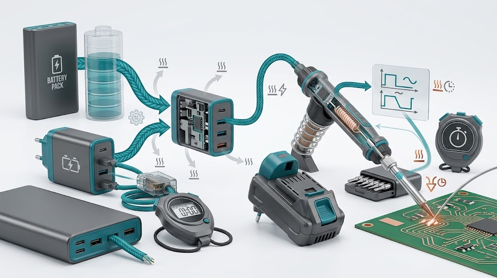
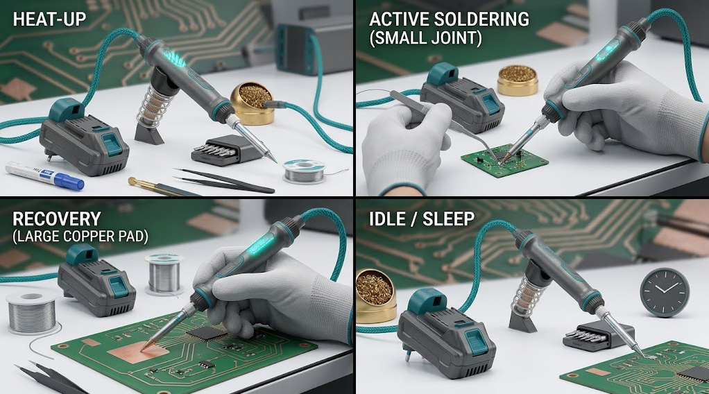
A cordless soldering iron may draw high power during heat-up or recovery and much less while maintaining temperature or sleeping. The heater's printed maximum is therefore not the same as the battery's average draw. Average power includes the controller, display, sensor, conversion stage, and any fan or light.Model the session in four states:
- Heat-up: the heater draws a high burst while reaching the selected range.
- Active joint: power varies as heat flows into solder, copper, wires, or connectors.
- Recovery: the controller increases heater power after a joint removes heat.
- Idle or sleep: the tool draws little power while parked, with occasional wake-up or reheating.
`average watts = (P1 x t1 + P2 x t2 + P3 x t3 + P4 x t4) / total time`
Use the same time unit for every state. If power is in watts and time is in hours, the result is watts. If you have no measured state powers, use a clearly labeled Estimated scenario.
Step 4: Include Duty Cycle in the Calculation
Duty cycle is the share of the session during which the heater actively replaces heat. A technician making short joints with long pauses can achieve a much lower average draw than someone continuously soldering heavy connectors. The same iron and battery can therefore produce very different runtimes.Example Calculated scenario:
- Heat-up: 60 W for 2 minutes
- Active soldering: 45 W for 12 minutes
- Recovery: 60 W for 6 minutes
- Idle: 5 W for 20 minutes
`(60 x 2/60) + (45 x 12/60) + (60 x 6/60) + (5 x 20/60) = 21.67 Wh`
Total session time is 40 minutes, or 0.667 hours. Average power is therefore:
`21.67 Wh / 0.667 h = 32.5 W average (Calculated)`
If usable energy were 27.54 Wh from the previous Estimated-factor example, the planning runtime would be:
`27.54 Wh / 32.5 W = 0.847 h, or about 51 minutes (Calculated)`
The result changes immediately if the operator spends more time on high-mass joints, if the source limits power, or if the battery is cold or aged.
Step 5: Account for Tip and Joint Thermal Load
The source can be electrically adequate while the joint still feels cold. A fine tip on a large ground plane may lose heat faster than the heater can restore it. A broader approved tip, clean wetting, a small solder bridge, and appropriate flux can improve heat transfer without raising temperature blindly.For runtime planning, record the tip geometry and joint type. A session made of small signal pads may spend more time in idle and recovery-light states. A session of shields, chassis tabs, or large copper areas may keep the controller near its recovery limit. Do not compare runtime tests unless tip, setpoint, solder, flux, workpiece, and duty cycle are documented.
QUICKO's T12 soldering tip range and black-finish T12 tip options help organize a tip plan, but compatibility is model-specific. Confirm the handle, controller, cartridge format, and approved temperature range before substitution.
Step 6: Calculate USB-C Soldering Iron Runtime Correctly
USB-C runtime requires one extra layer: the negotiated power contract. The USB Power Delivery specification overview explains that a source and sink negotiate available power. A power bank's cell rating, USB-C output, cable, sink controller, and converter losses all affect the energy that reaches the heater.Use this workflow:
- Read the iron's required and optional PD profiles from its manual.
- Record the power bank's documented output profile and energy basis.
- Confirm the cable's current and power rating and inspect both connectors.
- Test for shared-load behavior if the power bank also runs another device.
- Measure or estimate average input power at the source, not only heater peak power.
Sensitivity Analysis: Which Assumption Matters Most?
When inputs are uncertain, vary one assumption at a time. For the 27.54 usable Wh example:| Average power | Calculated planning runtime | Interpretation |
|---|---|---|
| 20 W | 1.38 h | Light joints and long idle periods |
| 30 W | 0.92 h | Moderate mixed duty cycle |
| 40 W | 0.69 h | More active soldering or recovery |
| 50 W | 0.55 h | Heavy duty cycle or high thermal load |
These are Calculated scenarios, not measured product results. A sensitivity table is more honest than one precise-looking runtime number because it shows how operator behavior and joint load change the answer.
Run a Controlled Runtime Test
To report a Measured runtime, define the test before starting:- Exact iron, controller revision, firmware, handle, and tip
- Exact battery or USB-C source, starting charge, charger, and cable
- Setpoint, sleep settings, boost settings, solder, flux, and workpiece
- Three representative joint types and their sequence
- Ambient temperature, ventilation, and workholding
- Start and stop criteria, timing method, and battery endpoint

Safety Boundaries for Runtime Testing
Stop and isolate the setup when you see:- Battery swelling, leakage, cracking, unusual odor, or abnormal heating
- Hot, loose, discolored, or intermittent cable or connector
- Smoke, arcing, sparks, exposed conductors, or damaged insulation
- Repeated low-voltage protection, resets, or source cycling
- Uncontrolled heater output or a display that cannot be trusted
- Unknown adapter, modified wiring, open mains charger, or missing manual
QUICKO Product Research Links
QUICKO's cordless soldering station catalog can help identify a battery-based architecture, but catalog fields may describe a specific configuration. Request the current manual, battery information, input profile, and accessories before using any number in a buyer-facing comparison.For broader system discovery, use the QUICKO product index and confirm whether a selected model is battery-powered, USB-C PD-powered, DC-input, or another design. Treat product-page runtime or power statements as manufacturer-provided until a defined first-party test is available.
Frequently Asked Questions
Is cordless soldering iron runtime based on heater wattage?
Not directly. Runtime depends on usable energy divided by average electrical power. Heater peak wattage affects heat-up and recovery, but the controller may cycle the heater, sleep, or spend time idle. Measure or estimate the complete duty cycle, including the controller and conversion losses.How do I calculate watt-hours from a battery label?
Multiply nominal volts by amp-hours. An 18 V, 2.0 Ah label gives 36 Wh as a Calculated nominal value. Apply an explicitly labeled discharge and efficiency factor to estimate usable energy. Do not present the nominal result as energy available at the tip or as measured runtime.Why is my measured runtime shorter than the formula?
The formula may have assumed too much usable energy or too little average power. Heavy copper joints, recovery bursts, cold batteries, cable losses, shared USB-C loads, battery aging, and protection reserve all reduce runtime. Re-run the test with documented tip, setpoint, duty cycle, source, and endpoint.Can I use a USB-C power bank with any portable iron?
No. The iron, power bank, cable, and negotiated PD profile must be compatible. A power bank may keep the display on while limiting heater current. Verify the manual and source documentation, then test idle and defined-load behavior with one approved configuration.Should I include idle time in a runtime estimate?
Yes. Idle and sleep time can materially lower average power, but wake-up and recovery still consume energy. Report active, recovery, and idle durations separately when possible. A continuous-heating test and an intermittent field-work test answer different questions and should not be compared as if they were the same workload.What is the best runtime number to publish for a product?
Publish a measured range only when the configuration and workload are documented. Include source, tip, setpoint, joint sequence, ambient condition, endpoint, repetitions, and whether the result is measured or calculated. If those controls are missing, publish the formula and evidence limits instead of a precise guarantee.Conclusion
To calculate cordless soldering iron runtime, start with watt-hours, reduce nominal energy to a documented or labeled usable estimate, calculate average power across the duty cycle, and validate the result with a controlled test. Peak heater wattage alone cannot tell you how long the tool will run.For QUICKO buyers, record the exact tool, battery or USB-C source, cable, tip, setpoint, joint sequence, and endpoint. Share that workload with the supplier and keep every result labeled Measured, Calculated, Estimated, or Unknown. If the source resets, heats abnormally, or shows battery damage, stop the test and escalate safely.


Linkedin:


