
 Tel:+86-13713635953
 Email:support@quicko.com.cn


How to Choose C210 Tip Shapes for Microsoldering?
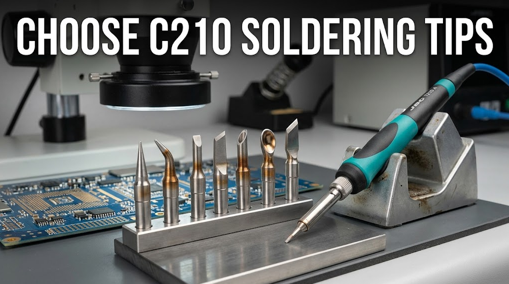
How to Choose C210 Tip Shapes for Microsoldering?
To choose C210 soldering tips, start with the joint rather than the tip catalog: select the largest wetted face that contacts both pad and lead without touching an adjacent conductor. Use a narrow chisel for most fine joints, a bevel or spoon for controlled solder delivery and drag work, and a bent shape when straight access blocks visibility. Confirm exact cartridge compatibility before purchase.Commercial disclosure: QUICKO publishes this guide and sells soldering stations, handles, cartridges, tips, and accessories. QUICKO links are commercial references. This article does not claim that every C210-style cartridge is interchangeable or that unverified QUICKO models match JBC dimensions, power, sensing, or electrical interfaces.
Direct Recommendation: Which C210 Shape Should You Start With?
For a first general-purpose microsoldering cartridge, choose a small chisel whose flat face can bridge the pad and lead while remaining clear of neighboring conductors. A chisel creates a more predictable contact patch than the point of a needle tip, so it usually transfers heat more efficiently at the same setpoint. Keep a fine conical or bent conical for exceptional access, and add a bevel or spoon only when the process benefits from carrying a controlled solder bead.Follow this six-step decision sequence:
- Inspect the joint geometry. Record pad width, lead width, pitch, exposed copper, nearby plastic, shields, and component height.
- Choose the largest safe face. The wetted face should touch pad and lead together but remain visibly clear of the next conductor.
- Match thermal load. Move to a larger face for ground-connected pads, connector tabs, or repeated joints; do not compensate for weak contact by automatically raising temperature.
- Check access and sight line. Choose a bent cartridge only when it improves approach angle or microscope visibility without creating lateral force.
- Verify compatibility. Match the exact station, handle, cartridge family, insertion depth, electrical interface, firmware, and supplier documentation.
- Validate on a coupon. Accept the choice only when three repeat joints wet promptly, avoid bridges and pad movement, and show consistent fillets without prolonged dwell.
Why the Smallest Tip Is Often the Wrong Tip
Heat enters a joint through the wetted contact area, not through the air around a sharp point. A very fine conical tip may touch a flat pad at only a tiny region. Oxide, imperfect angle, low solder coverage, and operator movement reduce that region further. The station can display the selected temperature while the joint still heats slowly because thermal coupling is poor.A chisel presents a flat face that can contact both lead and pad. A bevel or spoon offers a broader wetted surface and can retain solder for a controlled drag pass. Larger contact does not mean careless contact: the face must still fit the available clearance. The target is the largest usable face, not the largest cartridge in the drawer.
Long dwell creates risks that a higher setpoint does not solve cleanly. Flux can exhaust, tip plating can oxidize, nearby plastic can soften, and bonded copper can lift if the operator pushes or levers the joint. Use adequate flux, let the solder melt before moving the component, keep the tip force light, and stop when the pad or laminate begins to move.
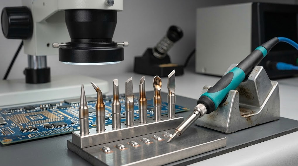
C210 Tip-Shape Comparison by Application
| Tip shape | Contact behavior | Best-fit tasks | Main limitation | Acceptance check |
|---|---|---|---|---|
| Fine conical | Small, angle-sensitive contact region | Isolated tiny pads, fine wire, confined rework | Slow transfer when only the point touches | Joint wets promptly without extra pressure or long dwell |
| Bent conical | Small contact with improved sight line and side access | Work beside shields, under microscope, awkward component orientation | Easy to apply lateral force or touch a neighbor | Operator can see the joint and approach without levering |
| Narrow chisel | Predictable flat face contacts lead and pad | Fine SMD joints, small passives, general microsoldering | Face can bridge at very tight pitch if oversized | Flat fits within clearance and wets both surfaces together |
| Medium chisel | Larger contact patch and greater usable thermal mass | Connector pins, small ground pads, repeated joints | Too broad for dense neighboring conductors | Recovery remains repeatable and adjacent pads stay untouched |
| Bevel or hoof | Broad angled face can carry a solder bead | Drag soldering gull-wing leads, tinning, solder delivery | Excess solder or poor angle can create bridges | Bead stays controlled and each lead separates after the pass |
| Spoon or knife | Extended edge or reservoir supports sweeping contact | Controlled drag work, edge access, specialized geometries | Technique-sensitive and not ideal for every isolated joint | Process produces repeatable fillets without scraping or bridging |
Manufacturer names are not perfectly consistent. “Bevel,” “hoof,” and “spoon” may refer to related but different working faces. Buy by the drawing and application, not by the label alone. The JBC example of a defined C210 chisel cartridge illustrates why a shape code, dimensions, and intended use should stay tied to one manufacturer’s documentation.
Key Specifications to Compare Before Buying
Working-face geometry
Ask for the face width, thickness, angle, radius, reach, and whether the usable surface is the point, side, flat, bevel, edge, or reservoir. Overall shaft appearance does not tell you the actual contact patch. A drawing or calibrated macro image is more useful than a name such as “micro” or “fine.”Clearance and approach
Measure the smallest distance to adjacent leads, shields, connectors, and plastic. Consider the whole cartridge body, not only its end. Under a microscope, a bent tip may make the joint visible while a straight tip and handle block the sight line. Confirm that the bend also leaves a neutral hand posture and does not encourage prying.Thermal demand
Compare the joint’s copper area, internal planes, connector mass, component lead size, and repetition rate. Tip shape changes the thermal path even when the station and setpoint remain unchanged. A tip that succeeds on one isolated pad may stall on an identical-looking pad tied to a ground plane.Wetting and plating condition
The selected face must wet evenly. Dark, pitted, de-wetted, or mechanically damaged plating reduces usable contact and makes a suitable geometry behave like an undersized one. Clean and tin only by the supplier’s approved method. Do not file plated tips to create a new shape.Cartridge and system compatibility
Confirm station model, handle model, cartridge family, physical keying, insertion depth, contact arrangement, sensor behavior, controller support, supply requirements, and regional documentation. A cartridge that slides into a handle is not automatically safe, correctly sensed, or calibrated. Browse the current QUICKO soldering products and cartridge categories to identify the exact product, then request its current manual or compatibility statement before ordering consumables.
Application-Based Selection Examples
Fine-pitch IC leads
Start with a narrow chisel that can touch one lead and its pad without spanning the next lead. For drag soldering, a small bevel or spoon may work better because it can carry solder across the row. Use flux and control the bead. Acceptance means separated leads, visible wetting, no solder balls, and no repeated heating to correct bridges.0201, 0402, and other tiny passives
Choose a small chisel or fine conical based on access. The chisel is preferable when its flat remains within the pad pair; the conical is useful when component height or surrounding parts restrict the approach. Stabilize the component with appropriate tools and never use the hot tip as a lever.Small ground-connected pads
Use the largest chisel face that safely fits. Apply suitable flux, ensure the face is freshly wetted, and preheat only when the board and process allow it. If the joint needs excessive dwell, investigate tip contact, board heat sinking, supply capability, and process setup before increasing temperature.Connector pins, shields, and tabs
These joints often need more contact area than their visible width suggests. A medium chisel, bevel, or specialized shape may couple heat better than a needle. Protect nearby plastic and stop if the connector body softens. For larger thermal loads, C245 or another appropriately rated system may be a better process choice; this article does not infer the boundary from an unverified QUICKO specification.Restricted access under a microscope
A bent conical or bent chisel can move the handle away from the sight line. Rotate the handle until the wetted face lies naturally on the joint. If maintaining contact requires side pressure, select a different angle or geometry.Compatibility, Consumables, and Procurement Controls
Treat “C210” as a family label that still requires model-level verification. Before buying a bulk pack, request a current drawing, compatible handle list, cartridge code, lot identification, storage guidance, warranty terms, and replacement policy. For third-party cartridges, also request confirmation of the intended station/controller combination rather than relying on marketplace titles.Maintain at least two validated shapes for a repair workflow: a narrow chisel for routine joints and a larger chisel or bevel for higher load or drag work. Add a bent tip only where it improves access. Keep each working face tinned during storage, use sleep or hibernation functions when supported, and quarantine cartridges with cracked insulation, loose shafts, damaged contacts, unstable recognition, or plating loss.
For general care questions, use the QUICKO soldering FAQ as a starting point, then follow the exact manual for the station and cartridge. General guidance cannot replace model-specific contact, calibration, or replacement instructions.
Controlled Selection Test and Acceptance Criteria
Use a representative scrap board or process coupon before a valuable assembly. The iFixit guide to soldering and desoldering connections provides general technique and safety context; your acceptance test still needs a defined configuration.- Record station, handle, cartridge code, tip geometry, supply, setpoint, solder alloy, flux, board, pad type, and ambient condition.
- Inspect the cold working face and confirm uniform tinning, intact plating, full insertion, and stable recognition.
- Make three repeat joints on the same geometry using the same preparation and operator sequence.
- Observe time to wet, dwell, recovery between joints, solder flow, visibility, hand angle, and any tendency to bridge or push the component.
- Inspect under magnification for complete wetting, appropriate fillet, separated conductors, undamaged mask, and no pad movement.
- Accept only if all three joints meet the same criteria without raising the setpoint to compensate for poor contact. Stop for unstable heating, abnormal handle temperature, damaged insulation, repeated bridges, pad lift, smoke, odor, or connector deformation.
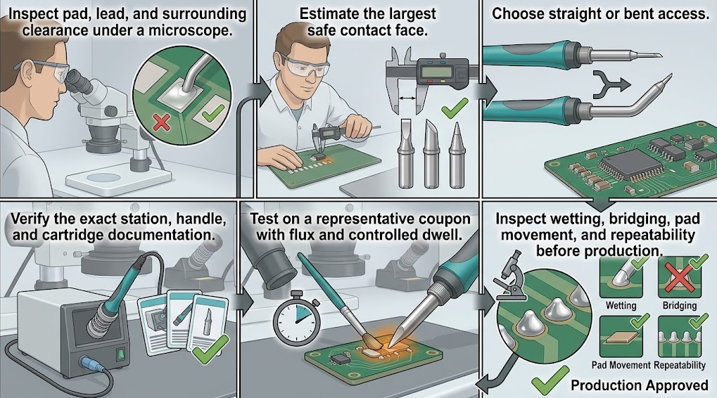
C210 Tip Selection Checklist
- What are the pad width, lead width, pitch, copper connection, and nearest clearance?
- Which wetted face can touch pad and lead at the same time?
- Does the proposed face remain clear of adjacent conductors through the full hand motion?
- Is straight or bent access more stable under the microscope?
- Does the process need point contact, a flat face, an edge, or a solder reservoir?
- Is the exact cartridge documented for the station, handle, controller, supply, and firmware?
- Are drawing, lot identity, replacement policy, and care instructions available?
- Do three repeat coupon joints meet wetting, dwell, recovery, bridge, pad, and visual criteria?
- Has a named technical reviewer checked any product-specific claim before publication?
Frequently Asked Questions
Is a conical C210 tip always best for microsoldering?
No. A fine conical tip offers access, but its small and angle-sensitive contact can transfer heat poorly to a flat or thermally connected pad. A narrow chisel often gives better coupling while remaining precise. Choose the largest face that safely fits the joint and verify it on a coupon.What is the best all-purpose C210 cartridge shape?
A small chisel is usually the strongest starting point because its flat face can contact a lead and pad together. “All-purpose” still depends on pitch, access, board copper, solder alloy, and station compatibility. Keep a second geometry for high-load or drag-soldering work.When should I choose a bevel or spoon tip?
Choose one when the task benefits from carrying a controlled solder bead, such as drag soldering a row of gull-wing leads or tinning a surface. Use adequate flux and validate the bead size. An oversized reservoir can bridge neighboring leads and obscure the joint.Does a C210 cartridge fit every C210 soldering iron?
Do not assume so. Similar names and physical fit do not prove the electrical interface, sensing method, insertion depth, controller support, or calibration are compatible. Confirm the exact station, handle, cartridge code, and supplier documentation before energizing the assembly.Should I raise temperature when a fine tip feels weak?
First check wetting, oxide, contact angle, face size, cartridge seating, joint heat sinking, and supply behavior. A larger safe contact face often transfers heat more effectively at the same setpoint. Raising temperature can accelerate oxidation and damage pads without correcting poor thermal coupling.Are Reddit tip recommendations reliable?
The r/soldering discussions about C210 are useful for discovering recurring problems and operator experiences. Treat them as anecdotal. Verify dimensions, compatibility, electrical facts, and safety limits against the current manufacturer documentation for the exact product.Conclusion
The best way to choose C210 soldering tips is to match the wetted contact face to the pad, lead, thermal load, access angle, and neighboring clearance. Start with a narrow chisel for routine microsoldering, use conical or bent shapes for restricted access, and select bevel, spoon, knife, or broader chisel geometries only when the joint and process justify them.Then verify the complete cartridge system and run three repeat coupon joints. A good selection wets promptly, recovers consistently, stays visible and controllable, avoids bridges, and protects pads and components without relying on excessive temperature or force. Check the latest QUICKO technical articles for related process guidance as product documentation and published evidence expand.


Linkedin:


