
 Tel:+86-13713635953
 Email:support@quicko.com.cn


How Does a Temperature-Controlled Soldering Station Work?
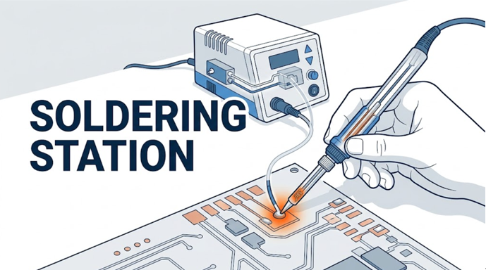
How Does a Temperature-Controlled Soldering Station Work?
A temperature-controlled soldering station works as a closed feedback loop. A sensor measures temperature near the heater or tip, the controller compares that measurement with the selected setpoint, and a power switch adjusts energy delivered to the heater. This cycle repeats so the tip can recover when a solder joint draws heat away.This guide is for electronics hobbyists, repair technicians, production operators, and buyers who want to understand the complete signal path inside a station. It covers sensing, signal conditioning, control logic, power switching, heater behavior, calibration, and fault diagnosis. It does not provide model-specific QUICKO ratings or authorize live-circuit repair; verify the manual, handle, cartridge, supply, grounding, and safety requirements for the exact system in use.
|
Commercial disclosure QUICKO publishes this technical guide and sells soldering stations, controllers, handles, cartridges, and tips. Product links lead to QUICKO pages. Physics and measurement references are identified separately, and competitor material is labeled as a manufacturer example rather than independent comparative proof. |
|---|
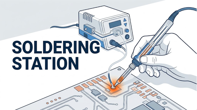
Key Takeaways
- A soldering station regulates temperature by measuring, comparing, switching, and measuring again.
- The setpoint is a controller target, not a guarantee that the solder joint is at exactly the same temperature.
- A sensor can be a thermocouple, a resistance-based element, or another temperature-dependent device; the control circuit must match it.
- PWM, burst control, or simple on/off switching describes how power is delivered. PID or proportional control describes how the controller decides how much power is needed.
- Tip geometry, thermal contact, heater placement, power-supply capacity, and control tuning all affect recovery under load.
- Calibration should use a suitable tip thermometer and a defined contact method, not an unloaded display reading alone.
Table of Contents
- What are the main parts of a soldering station?
- How does the closed feedback loop work?
- How does the station measure temperature?
- How does the controller decide heater power?
- How do PWM, MOSFETs, and triacs control the heater?
- Why does tip temperature drop during soldering?
- How is a station different from a fixed-power iron?
- How can you verify temperature and diagnose faults?
- What should you compare when choosing a station?
What Are the Main Parts of a Temperature-Controlled Soldering Station?
A station is easier to understand as five connected functional blocks rather than one appliance. The blocks may be distributed between the base unit, cable, handle, and cartridge, but the control problem remains the same.| Functional block | What it does | Typical implementation | Common failure effect |
|---|---|---|---|
| Setpoint and user interface | Defines the requested operating temperature | Knob, buttons, display, preset memory | Wrong target, locked setting, or confusing indication |
| Temperature sensor | Produces a signal related to local temperature | Thermocouple or resistance-based sensor | Open circuit, drift, polarity error, or unstable reading |
| Signal-conditioning and measurement circuit | Amplifies, filters, references, and digitizes the sensor signal | Amplifier, cold-junction compensation where required, ADC | Noise, offset, saturation, or incorrect scaling |
| Controller | Compares measured temperature with setpoint and calculates a command | Analog circuit or microcontroller firmware | Overshoot, slow recovery, cycling, or fault shutdown |
| Power stage and heater | Converts the command into controlled heat | MOSFET, triac, relay, transformer or DC supply, resistive heater | No heat, full heat, weak heat, or intermittent operation |
The tip and solder joint form the thermal load on this electrical control system. When the tip touches a copper pad, component lead, terminal, shield, or ground plane, heat flows out of the tip. The controller does not prevent that initial transfer; it detects the resulting change and commands more heater power.
For a component-level view of resistive heating and the thermal path through a handpiece, read QUICKO's guide to how a soldering iron heats up.
How Does the Closed Feedback Loop Work?
Closed-loop control means the result is measured and fed back into the decision. An uncontrolled iron applies power without using tip-temperature feedback. A temperature-controlled station repeatedly checks whether the measured temperature is below, near, or above the selected setpoint.The operating cycle can be described in seven steps:
- Set the target. The operator selects a temperature suitable for the solder alloy, joint mass, component limits, tip, and process.
- Measure the sensor. The station reads the thermocouple voltage, sensor resistance, or other temperature-dependent signal.
- Condition the signal. The circuit amplifies and filters the small sensor signal and converts it into a usable temperature estimate.
- Calculate the error. The controller subtracts measured temperature from the setpoint.
- Choose a power command. Control logic determines whether the heater needs full power, reduced power, or no power.
- Switch the heater. A MOSFET, triac, relay, or similar device delivers the commanded energy.
- Repeat. The next measurement shows whether the command reduced the error or whether the load changed again.
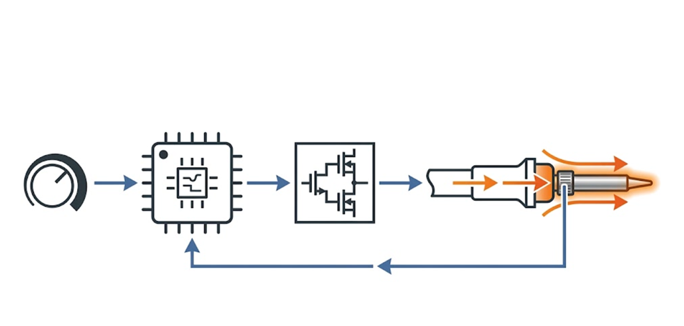
Figure 2. The station's closed loop runs from setpoint to controller, power stage, heater and tip, then back through the temperature sensor.
This loop is only as accurate as its measurement point and calibration. A sensor embedded behind the working surface measures its own location, not the exact solder-joint interface. Thermal resistance between the sensor and the wetted tip surface creates a difference that changes with tip construction, contact area, oxidation, and load.
How Does a Soldering Station Measure Temperature?
The station first converts temperature into an electrical signal. A thermocouple uses two dissimilar conductors and produces a small voltage related to a temperature difference. It therefore requires appropriate amplification and a reference or compensation method. The National Instruments thermocouple measurement reference explains the measurement principle and the role of reference-junction compensation.A resistance-based sensor works differently: its resistance changes with temperature. The controller applies a known excitation or measurement circuit, reads voltage or current, and converts the result using the expected sensor characteristic. A thermistor, resistance temperature detector, and heater element used as a sensor are not interchangeable merely because each changes resistance.
Three boundaries matter during design or troubleshooting:
- Sensor type: The controller must expect the correct voltage, resistance curve, polarity, and reference conditions.
- Sensor position: A sensor closer to the working end can observe changes sooner, but mechanical and electrical construction still affect the reading.
- Shared conductors: Some cartridge systems share heater and sensor connections or alternate heating and measurement intervals. Pin count alone does not establish compatibility.
How Does the Controller Decide How Much Heater Power to Apply?
The controller starts with an error value:Temperature error = setpoint - measured temperature
A large positive error usually calls for more power. An error near zero calls for less power, while a negative error means the measured value is above the target. Different stations translate that error into a power command in different ways.
| Control approach | Decision behavior | Strength | Tradeoff |
|---|---|---|---|
| On/off with hysteresis | Full power below a lower boundary; off above an upper boundary | Simple and robust | Temperature cycles around the target |
| Proportional control | Power changes in proportion to present error | Smoother near the setpoint | May retain steady-state error under a continuing load |
| PI control | Adds accumulated past error to proportional action | Can remove persistent offset | Poor tuning can create slow oscillation or overshoot |
| PID control | Adds a term related to rate of change | Can improve transient response when tuned well | More sensitive to noise and tuning choices |
Not every digital station uses PID, and not every PID-controlled station behaves well. Sensor delay, heater power, tip mass, sampling rate, filtering, command limits, and tuning must work as one system. A control label by itself does not predict recovery or stability.
The controller should also handle abnormal states. A disconnected sensor, implausible reading, stalled warm-up, or shorted output should lead to a fault response rather than unlimited heating. The exact protections are product-specific and must be confirmed in the applicable documentation.
How Do PWM, MOSFETs, and Triacs Control the Heater?
The control algorithm produces a requested power level, but a semiconductor or relay must carry the heater current. In low-voltage DC stations, a MOSFET commonly switches the heater supply. In AC-powered arrangements, a triac may control whole or partial mains cycles. The topology, isolation, grounding, and protection requirements differ, so one circuit should not be assumed equivalent to another.Pulse-width modulation, or PWM, changes the percentage of time that a switch is on within a repeating period. A 100% command keeps the switch on continuously for that interval; a 50% command applies energy for roughly half of it. Burst or time-proportioning control groups complete on and off intervals. Both can vary average heater power, but their switching time scale and electrical effects differ.
PWM is not the same thing as PID. PID is a decision method; PWM is one actuation method. A proportional, PI, PID, or even fixed-duty command can be delivered through PWM. Conversely, a controller can use on/off decisions without a high-frequency PWM waveform.
Heater power follows the familiar electrical relationships:
P = V x I
P = I^2 x R
P = V^2 / R
OpenStax derives these relationships in its explanation of electric power and energy. For a simplified 8-ohm heater supplied with 24 V, the ideal calculation is 24^2 / 8 = 72 W. At 12 V, the same constant-resistance assumption gives 12^2 / 8 = 18 W. These are calculation examples, not QUICKO product ratings; real resistance, supply limits, switching losses, cable resistance, and control duty affect delivered power.
Why Does Tip Temperature Drop When It Touches a Joint?
The tip contains stored thermal energy. Touching a colder pad and lead creates a heat-flow path, so energy leaves the tip and warms the work. A large ground plane, shield can, connector shell, or heavy terminal can absorb heat faster than a small surface-mount pad.The station responds after the sensor observes the disturbance. Recovery therefore depends on more than idle display accuracy:
- available electrical power at the heater;
- distance and thermal resistance from heater to working surface;
- sensor distance and response time;
- tip mass, shape, plating condition, and contact area;
- solder bridge and flux behavior at the joint;
- controller sampling, filtering, limits, and tuning;
- power-supply voltage stability and cable or connector losses.
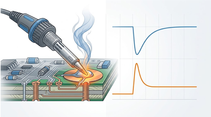
Raising the setpoint is not always the best response to slow soldering. A broader tip can increase contact area and transfer heat more efficiently at the same setpoint. Cleaning and tinning the working surface can improve the solder bridge. Increasing temperature without fixing poor contact can accelerate oxidation and increase thermal stress on the board.
Cartridge systems place the heater and sensor close to the working end, shortening parts of the thermal and measurement path. JBC describes this integration in its manufacturer overview of an efficient soldering heating system. That page illustrates the architecture; it is not used here to claim that one brand or cartridge is universally faster than another.
How Is a Temperature-Controlled Station Different from a Fixed-Power Iron?
A fixed-power iron is governed mainly by the balance between incoming heater power and heat lost to air, the stand, and the work. Its unloaded temperature can rise until heat loss matches input, then fall sharply on a large joint. The operator has limited ability to define or verify a stable working temperature.A controlled station adds measurement and correction. It can reduce power as the setpoint approaches, then increase power when the joint becomes a load. This improves repeatability, but it does not eliminate process variation. An unsuitable tip, damaged sensor, insufficient supply, poor calibration, or incorrect compatibility can still produce weak joints or excessive heat exposure.
How Can You Verify a Soldering Station's Temperature?
Display temperature and working-surface temperature are related but not identical. To compare stations or verify one after service, use a repeatable method rather than touching an ordinary probe casually to the tip.- Use a suitable tip thermometer. Confirm the sensor, measurement range, condition, and instructions are appropriate for soldering tips.
- Fit the intended tip. Record the tip family, shape, size, condition, and whether it is freshly tinned.
- Allow stabilization. Let the station reach the setpoint and complete its normal stabilization period.
- Create consistent contact. Apply the same small solder bridge and contact position each time, following the thermometer manufacturer's procedure.
- Repeat and record. Take multiple readings at the same setpoint and method. Record the spread as well as the most favorable value.
- Test recovery separately. Apply a defined thermal load and record minimum temperature and time to return to a chosen band. Do not mix this with idle calibration.
How Do You Diagnose Common Temperature-Control Problems?
Disconnect power and let the station cool before inspecting a handle, cable, connector, cartridge, or controller. Do not open a mains-powered station or probe energized circuits unless you are qualified and have the correct isolation and test equipment.| Symptom | Possible control-path cause | Safer first check |
|---|---|---|
| No heat | Open heater, absent supply, output switch not driven, protection active | Confirm compatible handpiece, seated connector, fuse/manual indications, and known-good tip where approved |
| Full uncontrolled heat | Sensor open or reversed, measurement circuit fault, shorted power switch | Switch off immediately; do not continue testing at the tip |
| Slow warm-up | Low supply voltage, current limit, high connector resistance, weak heater | Verify specified supply and compatible heater; inspect connector condition when cool |
| Large overshoot | Sensor delay, excessive integral action, wrong sensor type, poor thermal contact | Restore documented settings and verify matched handle/cartridge/controller |
| Temperature flicker | Intermittent cable, oxidized contacts, switching noise, unstable reference | Inspect cable and connector movement when de-energized; substitute only confirmed-compatible parts |
| Good idle reading but weak joints | Small tip, poor wetting, distant sensor, high-mass load | Use a suitable clean tinned tip and evaluate recovery under a defined load |
QUICKO's older comparison of T12 and 936 heating behavior provides additional product-family context. Treat its numerical examples as page-specific claims that should be reconfirmed against the actual cartridge, supply, and controller before publication or purchasing decisions.
What Should You Compare When Choosing a Soldering Station?
Do not choose from maximum temperature alone. A high display limit says little about heat transfer, recovery, sensing, or safety.Use the following decision checklist:
- Work type: Fine-pitch boards favor compact tips and low handpiece mass; connectors and ground planes need stronger thermal delivery and suitable contact area.
- Heater and sensor architecture: Check whether the heater and sensor are integrated in a cartridge or separated by mechanical interfaces.
- Rated system power: Confirm the station, supply, handle, and cartridge ratings as one matched system.
- Recovery evidence: Prefer a documented load method over an unloaded warm-up claim.
- Tip ecosystem: Compare available shapes, sizes, cost, plating care, and replacement supply.
- Control and safety features: Verify calibration procedure, sleep behavior, fault detection, grounding, isolation, and region-appropriate power requirements.
- Compatibility: Similar names or dimensions do not prove electrical or control compatibility.
- Serviceability: Consider connector quality, cable replacement, firmware support where applicable, and access to documentation.
Safety Note
A soldering station creates burn, fire, fume, molten-metal, and electrical hazards. Use a stable stand, eye protection appropriate to the task, local fume control, and good hygiene, especially when lead-containing solder may be present. Keep the cable and hot tip away from insulation and skin. Disconnect power before changing internal wiring, and follow the station, solder, flux, and workplace safety instructions.Frequently Asked Questions
Does a soldering station keep the tip at exactly the set temperature?
No. The display shows a measured or calculated value at a sensor location, while the working surface and joint can differ. Sensor placement, calibration, tip construction, load, and control timing create error. A suitable tip thermometer can verify a defined contact method, but it still does not measure every point in a live joint.Is PID always better than on/off temperature control?
Not automatically. PID can improve response when the sensor, heater, sampling, filtering, limits, and tuning are well matched. Poor tuning can overshoot or oscillate. A simple hysteresis controller may be stable and adequate for some loads. Evaluate measured recovery and stability rather than choosing from the control label alone.Why does the temperature display stay stable while solder melts slowly?
The sensor may be closer to the heater than the joint, so it can report a stable local temperature while the working surface cools. A narrow or oxidized tip, weak solder bridge, large copper plane, loose interface, or limited supply can also restrict heat flow even when the display looks normal.Does higher wattage always make a soldering station better?
Higher available power can improve warm-up and recovery, but only when the supply, heater, sensor, controller, tip, and joint contact can use it safely. Tip geometry and thermal resistance often determine how effectively power reaches the joint. Compare system behavior under a defined load, not wattage in isolation.Can any T12, C210, or C245-style handle work with any controller?
No. Family names and similar connectors do not prove compatibility. Heater resistance, sensor type, shared conductors, pinout, supply voltage, grounding, firmware logic, and connector rating can differ. Use only combinations confirmed by the station, handle, and cartridge documentation; an incorrect pairing can cause faults or uncontrolled heating.Conclusion
A temperature-controlled soldering station works by closing the loop between heat and measurement. The sensor reports temperature, the controller compares it with the setpoint, the power stage drives the heater, and the tip transfers energy into the joint. Stable soldering depends on the entire path, not on the display or wattage alone.For practical selection, match the station to the joint size, tip ecosystem, cartridge architecture, supply, calibration method, and safety requirements. Then verify the assembled system with a repeatable idle and recovery test before relying on it for production or delicate repair.


Linkedin:


