
 Tel:+86-13713635953
 Email:support@quicko.com.cn


How Does a T12 Soldering Station Work? Complete Guide

How Does a T12 Soldering Station Work?
A T12 soldering station controls a cartridge tip that contains the working tip, heater, and temperature sensor in one compact assembly. The controller applies power, pauses or separates the drive as its circuit requires, reads the temperature signal, compares it with the setpoint, and adjusts the next power command. The short thermal path helps the tip respond quickly when a joint removes heat.This guide is for technicians, electronics hobbyists, production operators, and buyers who want to understand what is inside a T12 system before selecting or using one. It covers the cartridge, handle, controller, power stage, first startup, compatibility, calibration, thermal recovery, and common faults. It does not assign one specification to every T12 product. Always confirm the manual, supply voltage, connector pinout, grounding, firmware, handle sensor, and cartridge compatibility for the exact station.
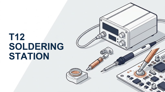
Figure 1. A T12 soldering station combines a controller, power stage, handle, and integrated cartridge tip in one temperature-regulated system.
Key Takeaways
- A T12 cartridge places the tip, heater, and sensor close together, reducing thermal distance compared with a separate heater and slip-on tip.
- The controller does not simply feed constant power. It measures temperature, calculates error, switches heater power, and repeats the cycle.
- A 24 V supply and an approximately 8 ohm heater would produce an ideal 72 W only under the simplified constant-resistance calculation. That is not a universal T12 rating.
- The display setpoint is a control target. Actual tip and joint temperature also depend on calibration, tip geometry, contact area, solder alloy, flux, and thermal load.
- Handle wiring, connector pinout, motion switches, grounding, firmware, and calibration data can differ even when two products accept T12-style cartridges.
- Buyers should compare recovery under a representative load, not warm-up time alone.
Table of Contents
- What makes a T12 system different?
- What parts are inside a T12 soldering station?
- How does the T12 cartridge produce and measure heat?
- How does the controller regulate temperature?
- How should you set up a T12 station for the first time?
- Why does thermal recovery matter?
- What must be compatible in a T12 system?
- How do you diagnose common T12 faults?
- What should buyers compare?
What Makes a T12 Soldering Station Different?
The defining feature is the cartridge. In a traditional assembly, a ceramic heater sits inside or near a removable metal tip. Every interface between heater, air gap, sleeve, and tip adds thermal resistance. A T12-style cartridge integrates the heater and sensor with the working tip, so heat and measurement travel through a shorter, more repeatable path.HAKKO describes its composite T12/T15 tip as a soldering tip integrated with a heating element and sensor. The company's FX-952 technical overview also links this construction to thermal response and recovery. That source documents HAKKO's architecture; it does not prove that every third-party cartridge, controller, or station performs identically.
The integration changes service and selection decisions. Replacing the cartridge also replaces the heater and sensor associated with that working end. It makes tip geometry, cartridge construction, electrical contact quality, and calibration part of one system decision. QUICKO's overview of why T12 soldering stations are popular discusses the practical appeal of temperature control, recovery, interchangeable tips, and cost.
| Architecture | Heater and sensor location | Thermal interfaces | Service implication | Selection risk |
|---|---|---|---|---|
| T12-style cartridge | Integrated with the removable working tip | Short path within one cartridge | Cartridge replacement changes tip, heater, and sensor together | Cartridge quality and calibration can vary |
| Separate ceramic heater with slip-on tip | Heater remains in the handpiece; metal tip fits over it | More mechanical interfaces between heater and joint | Heater and metal tip can be replaced separately | Fit, oxidation, and air gaps affect heat transfer |
| Other cartridge families | Integrated, but with their own dimensions and contacts | Short path within a family-specific design | Replaceable cartridge | Similar appearance does not mean electrical compatibility |
What Parts Are Inside a T12 Soldering Station?
A complete station is more than its tip. The base, handle, cable, connector, and cartridge form one electrical and thermal chain. Some functions may move between the base and handle, but each system needs the following jobs to be performed.| Functional block | Job | Typical implementation | What to verify |
|---|---|---|---|
| DC power source | Supplies heater energy and controller power | Internal or external regulated supply | Voltage, current limit, isolation, grounding, connector |
| User interface | Sets temperature and operating mode | Encoder, buttons, display, presets | Units, limits, lock, calibration menu |
| Measurement circuit | Converts the small sensor signal into a temperature estimate | Amplifier, filter, ADC, firmware correction | Sensor type, polarity, noise control, calibration |
| Controller | Compares measured temperature with the selected target | Microcontroller with on/off, proportional, PI, or PID logic | Firmware behavior and fault handling |
| Power switch | Connects and disconnects heater current | MOSFET or another switching device | Voltage/current rating, heat sinking, failure mode |
| Handle and cable | Carries heater, sensor, ground, and optional motion signals | Cartridge contacts, flexible cable, connector | Pinout, contact condition, strain relief, protective earth |
| T12 cartridge | Produces heat, senses temperature, and contacts the joint | Integrated tip, heater, sensor, conductors | Shape, plating, resistance, fit, calibration offset |
Optional features are not part of the basic T12 definition. Motion sensing, stand detection, boost mode, multiple presets, buzzer behavior, password locks, and handle-temperature monitoring depend on the handle and firmware. Treat them as station features, not guaranteed properties of every T12 cartridge.
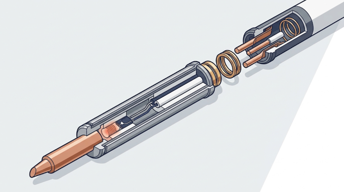
Figure 2. The T12 cartridge shortens the physical path between the heater, sensing region, working tip, and handle contacts.
How Does the T12 Cartridge Produce and Measure Heat?
The heater is a resistive load. When the controller applies voltage, current flows and electrical energy becomes heat. The simplified relationships are `P = V x I`, `V = I x R`, and therefore `P = V^2 / R` for an ideal constant resistance. OpenStax explains these equations in its reference on electric power and energy.QUICKO's older comparison of T12 and 936-style heating uses an approximately 8 ohm T12 example. Under the ideal equation, 24 V across 8 ohms gives `24^2 / 8 = 72 W`; 12 V gives `12^2 / 8 = 18 W`. Those figures show why supply voltage matters. They are not guaranteed cartridge ratings because resistance changes with temperature, and real supplies, switches, cables, contacts, and firmware limit delivered energy.
The sensor produces a small signal related to temperature. A thermocouple generates voltage from a temperature difference between junctions of dissimilar conductors. The measurement circuit must amplify and reference that signal correctly. The National Instruments thermocouple measurement guide explains why reference-junction treatment, noise, and connection materials matter when converting a small thermoelectric voltage into a temperature estimate.
In many T12 controller designs, heating and sensing cannot be treated as two completely independent wires and continuous operations. The circuit creates a suitable measurement interval, suppresses switching interference, samples the sensor path, and then resumes the commanded drive. The exact contacts, timing, polarity, amplification, and protection network belong to the controller and handle design. Do not copy a pinout or calibration constant from an unrelated station.
How Does a T12 Soldering Station Control Temperature?
The control loop repeats the same six decisions many times per second, although the exact sampling and switching rates vary by controller.- Read the setpoint. The station obtains the operator's selected temperature or a standby target.
- Create a measurement condition. The power stage enters the state required for a clean sensor reading.
- Measure temperature. The analog circuit and ADC convert the cartridge signal into a digital value.
- Calculate error. Firmware compares the estimated tip temperature with the setpoint.
- Choose heater energy. The controller commands more, less, or no power according to its control law and limits.
- Check faults and repeat. Open sensors, impossible readings, overtemperature, supply problems, or idle timers can change the next action.
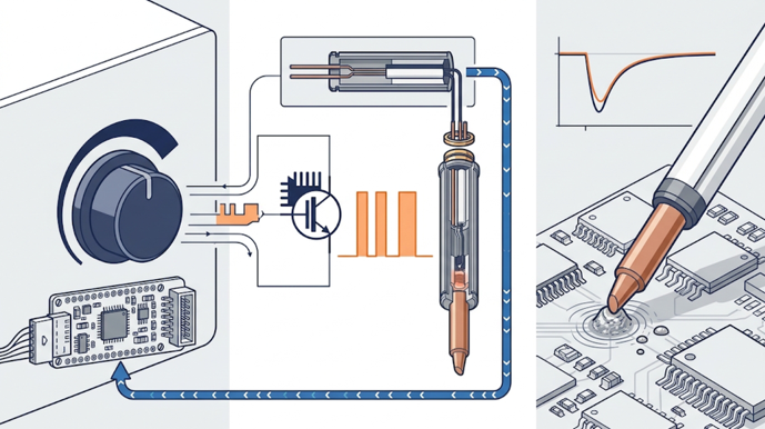
Figure 3. A controller alternates measurement, calculation, and heater switching while the cartridge transfers heat into the joint and the sensor feeds temperature information back.
How Do You Set Up a T12 Soldering Station for the First Time?
First startup should confirm compatibility and safety before temperature performance. A display that lights up does not prove that the cartridge, handle, connector, grounding, and firmware match.Step 1: Verify the system before applying power
Check the station label and manual for input voltage, DC supply requirements, protective-earth arrangement, fuse rating, handle type, and connector pinout. Inspect the cable, strain relief, cartridge contacts, enclosure, and stand. Do not energize a unit with exposed mains conductors, a damaged cable, loose metalwork, or uncertain grounding.Step 2: Insert the correct cartridge cold
With power off and the tip cool, insert the cartridge according to the handle instructions. It should seat fully without forcing, twisting damaged contacts, or leaving an unstable electrical connection. Use a heat-resistant removal pad for later changes and follow the cartridge supplier's hot-change guidance.Step 3: Start at a process-appropriate setpoint
Choose temperature from the solder alloy, flux, component limits, joint mass, tip geometry, and dwell-time target. Do not use a higher number to compensate for an oxidized tip, poor contact, undersized geometry, or weak supply. Those faults can overheat small joints without fixing heat transfer into larger ones.Step 4: Tin the working surface
Apply a small amount of compatible solder and flux to protect the working surface and improve thermal contact. Keep the wettable area bright and coated. Abrasive cleaning can remove plating, so use the cleaning method recommended for the cartridge rather than filing the tip.Step 5: Verify stability and recovery
Allow the station to stabilize, then check the display for oscillation or fault codes. If accuracy matters, use a suitable tip thermometer with a repeatable contact method. Test recovery on a representative copper load rather than judging only the unloaded warm-up animation.Step 6: Configure standby conservatively
If the handle and firmware support motion or stand detection, set a lower idle temperature and a later sleep or shutdown condition. Confirm that the station actually enters and exits these modes. A feature listed in a menu is useful only when the correct sensor and wiring make it work.Why Does Thermal Recovery Matter More Than Warm-Up Time?
Warm-up time measures how quickly an unloaded tip reaches a target from ambient temperature. Soldering adds a different problem: a pad, lead, connector, shield, or ground plane pulls heat out of the tip. The controller must detect the drop and deliver enough energy through the cartridge to restore the process temperature.Recovery depends on more than rated watts. It changes with supply voltage under load, current limiting, heater resistance, switch losses, contact resistance, tip mass, tip shape, plating condition, firmware tuning, and the thermal contact area at the joint. A broad chisel can transfer more heat into a wide pad than a needle tip even when both use the same station.
A useful comparison test records at least five fields: starting setpoint in degrees Celsius, tip geometry, copper-load description, minimum measured temperature after contact, and time to return within a defined band such as 10 degrees Celsius of the setpoint. Without the same tip, load, method, and threshold, two recovery claims are not directly comparable.
What Must Be Compatible in a T12 System?
The label "T12" is necessary but not sufficient. A cartridge may fit mechanically while the handle wiring, connector, ground path, firmware, calibration, or power source differs.| Compatibility check | Why it matters | Safer verification |
|---|---|---|
| Cartridge dimensions and contact condition | Poor seating creates intermittent heat or sensor errors | Compare drawings and inspect contacts before power-up |
| Handle contact arrangement | Heater and sensor paths must reach the correct controller inputs | Use the exact handle/controller wiring diagram |
| Station connector pinout | Similar connectors can be wired differently | Verify every pin from the manual, not connector appearance |
| Supply voltage and current | Wrong supply can cause weak heat, resets, or damage | Match rated input and required current margin |
| Protective earth and tip ground | ESD control and electrical safety depend on the complete path | Test using the manufacturer's procedure and suitable meter |
| Motion or stand sensor | Standby behavior depends on sensor type and wiring | Confirm the feature with the intended handle |
| Firmware and tip profile | Calibration and control tuning may be profile-specific | Use supported firmware settings and verify temperature |
For current catalog options, review QUICKO's T12 stations, handles, controllers, and tips. Confirm the individual product manual before ordering or combining parts; the category page is a product entry point, not a universal compatibility statement.
How Do You Diagnose Common T12 Soldering Station Faults?
Start with the lowest-risk checks. A live station contains hot surfaces and may contain hazardous mains voltage. Disconnect power and allow the cartridge to cool before opening a handle or enclosure. Internal mains-side diagnosis belongs to a qualified person with the correct isolation and measurement practices.| Symptom | Likely area | First safe checks | Avoid |
|---|---|---|---|
| Display works but tip stays cold | Cartridge seating, heater path, supply limit, MOSFET command | Reseat a cool approved cartridge; inspect contacts; confirm correct supply | Bridging the heater switch or applying power directly |
| Temperature jumps or shows sensor error | Sensor path, contact contamination, cable, connector, polarity | Try a known-compatible cartridge; inspect and clean approved contacts; flex-test cable unpowered | Copying another model's pinout |
| Slow heating and weak joints | Low supply voltage, current limiting, high contact resistance, unsuitable tip | Measure supply behavior under load; inspect connectors; use appropriate tip geometry | Raising setpoint without finding the heat-transfer problem |
| Severe overshoot or glowing tip | Missing sensor feedback, wrong profile, failed power switch | Power off immediately; check cartridge and firmware compatibility | Continuing to heat or touching the tip to a board |
| Station resets when heating | Supply collapse, cable fault, controller protection | Confirm supply rating and connector condition | Installing a larger fuse to hide the fault |
| Standby never activates | Motion/stand sensor mismatch, wiring, firmware setting | Confirm handle sensor type and menu support | Assuming every T12 handle includes the same sensor |
Three substitutions isolate many problems: a known-good compatible cartridge, a known-good compatible handle, and a verified supply. Change only one item at a time and record the result. This prevents a second mismatch from hiding the first fault.
What Should You Compare Before Buying a T12 Soldering Station?
Compare the entire system rather than the largest number on the product page.- Verified input and output design: Check supply voltage, continuous current capability, isolation, fuse, enclosure, and grounding documentation.
- Recovery evidence: Look for a repeatable load test with tip geometry, setpoint, minimum temperature, and recovery threshold.
- Handle and cartridge support: Confirm connector pinout, cartridge fit, cable flexibility, strain relief, ground path, and available tip shapes.
- Control and calibration: Check whether offset calibration, supported profiles, fault detection, standby, sleep, and lock functions are documented.
- Serviceability: Confirm replacement handles, cartridges, connectors, supplies, manuals, and support access.
- Process fit: Fine PCB repair, connectors, wire, shields, and large copper areas need different tip geometries even when one controller powers them.
Frequently Asked Questions
Is every T12 soldering iron tip compatible with every T12 station?
No. The cartridge may share a T12-style shape, but the handle contacts, station connector pinout, ground path, firmware profile, calibration, and supply can differ. Verify the cartridge, handle, and controller documentation as one system. Mechanical fit alone does not prove safe electrical or measurement compatibility.Does a T12 soldering station always use PID control?
No. T12 describes a cartridge family, not one control algorithm. A station may use on/off, proportional, PI, PID, or another firmware strategy, and it may switch power with PWM or another timing method. Judge the controller by measured stability, recovery, overshoot, and documented fault behavior rather than the PID label alone.Why does a T12 tip heat quickly?
The heater, sensor, and working tip are integrated into a compact cartridge, which shortens the heat path and reduces thermal interfaces. Heater power and low moving thermal mass can also reduce warm-up time. Actual speed still depends on cartridge resistance, supply voltage, current limit, contact quality, firmware, and tip geometry.What voltage does a T12 soldering station use?
Many bench T12 systems use a nominal 24 V supply, but T12 does not guarantee one voltage. Portable and third-party designs can differ. Read the exact station and controller ratings before connecting power. The same heater supplied at 12 V receives far less ideal power than at 24 V under a constant-resistance calculation.How can I tell whether the displayed temperature is accurate?
Use a suitable soldering-tip thermometer, a defined contact method, fresh solder or the specified sensor contact, and repeated readings after stabilization. Record the tip shape, setpoint, ambient conditions, and measurement spread. Then test recovery separately under load; an accurate unloaded reading does not prove stable temperature during soldering.Conclusion
A T12 soldering station works by placing the heater and sensor inside the removable cartridge, measuring the resulting temperature signal, comparing it with the setpoint, and switching heater energy to correct the error. Its useful performance comes from the complete chain: supply, controller, contacts, handle, cartridge, tip geometry, calibration, and thermal load.Before buying or combining parts, verify voltage, current, pinout, grounding, handle sensors, firmware support, and cartridge fit. Then compare recovery with the same tip and copper load. That evidence gives a better decision than a warm-up claim or maximum temperature alone.
Publication Safety Note
Soldering creates burn, fire, electrical, molten-metal, and fume hazards. Use eye protection, a stable stand, ventilation or appropriate fume control, heat-resistant handling tools, and the solder and flux safety data supplied for the process. Wash hands after handling lead-containing materials. Disconnect power before servicing, and do not open mains-powered equipment unless you are qualified to work safely on it.Sources and Evidence Boundaries
- HAKKO Corporation, FX-952 product and composite-tip overview, accessed August 17, 2026. Manufacturer source for HAKKO's T12 architecture and feature descriptions; not independent comparative proof.
- National Instruments, Thermocouple measurement reference, accessed August 17, 2026. Used for thermocouple measurement principles and error sources.
- OpenStax, Electric Power and Energy, accessed August 17, 2026. Used for the electrical power equations.
- QUICKO, Why T12 iron tip heating faster than 936 iron tip?, accessed August 17, 2026. First-party historical page used for the approximate 8 ohm example; confirm against the exact cartridge before publication or purchasing decisions.
- Competitor content reviewed for coverage gaps only: Quecoo, RCHelicopterFun, and Hackaday. No competitor performance or product claim is presented as QUICKO evidence.


Linkedin:


