
 Tel:+86-13713635953
 Email:support@quicko.com.cn


C210 Soldering Iron Guide for Precision Electronics Work
C210 Soldering Iron Guide for Precision Electronics Work
A C210 soldering iron is a precision cartridge system built around a small replaceable tip-and-heater assembly. The cartridge sits in a compatible handpiece, while a controller measures temperature and switches heater power to hold the selected process temperature. The compact geometry makes C210 systems useful for fine-pitch boards, microscope rework, connectors, and other joints where tip access matters as much as raw wattage.This guide is for electronics hobbyists, repair technicians, production operators, and buyers comparing C210 handles, cartridges, controllers, and stations. It explains what the C210 format is, how its parts work together, how tip shape changes the job, and how to verify compatibility before applying power. It does not treat one JBC, QUICKO, or third-party product page as a universal specification. Confirm the exact manual, connector, sensor arrangement, supported cartridge family, voltage, and grounding path for the station you own.
Figure 1. A C210 soldering iron pairs a small precision cartridge with a compatible handpiece and temperature controller for fine electronics work.
Key Takeaways
- C210 usually refers to a compact cartridge family, not a complete soldering station. The cartridge, handle, controller, cable, and power source must be treated as one system.
- JBC describes its C210 range as suitable for precision soldering with medium power requirements, including SMD work under a microscope and conventional components.
- Tip geometry determines access and heat transfer. A fine conical tip reaches small pads, a chisel supports pin rows, and a bevel or spoon can carry more solder to a broader joint.
- Mechanical fit is not enough. Check handle contacts, sensor wiring, controller firmware, supply limits, tip grounding, and calibration support before mixing parts.
- Display temperature is a control target, not a guarantee that the joint reaches the same temperature. Tip mass, copper area, contact time, solder, flux, and measurement method all matter.
- Buyers should compare repeatable recovery and compatibility evidence, not only the largest temperature or power number in a listing.
Table of Contents
- What is a C210 soldering iron?
- What parts make up a C210 system?
- How does a C210 cartridge heat and sense temperature?
- Which C210 soldering tip shape should you choose?
- What is the difference between C210, C245, and T12?
- How do you verify C210 compatibility?
- How do you set up and calibrate a C210 station?
- How do you diagnose common C210 faults?
- What should buyers compare before ordering?
What Is a C210 Soldering Iron?
A C210 soldering iron is a precision handpiece and cartridge arrangement used to heat small or medium electronic joints under closed-loop temperature control. In the JBC naming system, C210 identifies a cartridge range, while T210 identifies a compatible precision handle family. A controller and power stage sit upstream of the handle; they are not automatically included when a seller says “C210 tip” or “C210 iron.”JBC describes its C210 cartridge range as suitable for precision soldering jobs with medium power requirements. The page specifically mentions SMD work under a microscope and conventional components, then groups cartridges by conical, chisel, bevel, spoon, barrel, knife, coating-removal, and specialized designs. Those categories explain the use case, but they do not prove that every third-party C210-style cartridge has the same heater resistance, sensor behavior, plating, or life.
The most useful mental model is a small, serviceable thermal path. The working surface, heater, and sensor are close together inside the cartridge. The handpiece holds that cartridge at a repeatable angle and routes heater, sensor, and ground contacts to the controller. A shorter path can improve responsiveness, but the finished joint still depends on contact area, copper mass, tip condition, flux, and process timing.
For background on the electrical-to-tip path, see QUICKO's soldering iron heating explanation. It explains why a controller, heater, sensor, and tip must be evaluated together instead of treating the iron as a simple resistive stick.
What Parts Make Up a C210 System?
The label on the cartridge is only one part of the system. Before buying a replacement or building a bench setup, map these functions and confirm where each one lives.| System part | What it does | What to verify |
|---|---|---|
| C210 cartridge | Transfers heat to the joint and provides the sensing element used by the controller | Shape, contact layout, resistance, sensor type, plating, and supported station |
| Precision handpiece | Holds the cartridge, provides insulation, and routes electrical contacts | T210 or compatible handle family, grip, contact depth, cable, and ground path |
| Temperature controller | Reads the sensor, compares it with the setpoint, and commands heater power | Supported cartridge family, calibration menu, fault behavior, temperature limits |
| Power stage | Converts supply energy into controlled heater current | Input voltage, current limit, switch rating, isolation, and thermal protection |
| Stand or sleep sensor | Reduces temperature or turns the heater off when the iron is parked | Handle sensor type, stand detection, firmware mode, and wake behavior |
| Tip or cartridge holder | Protects the hot cartridge and helps prevent mechanical damage | Heat resistance, safe removal method, and storage position |
JBC's T210 handle information is a useful reminder that cartridge and handle compatibility are linked. A connector that looks similar can still route sensor or ground contacts differently. QUICKO's C210/245 cordless product page is a live example of why buyers should read the exact listing: the page combines C210 and C245 language, gives product-specific voltage and power fields, and tells buyers to confirm battery suitability before ordering.
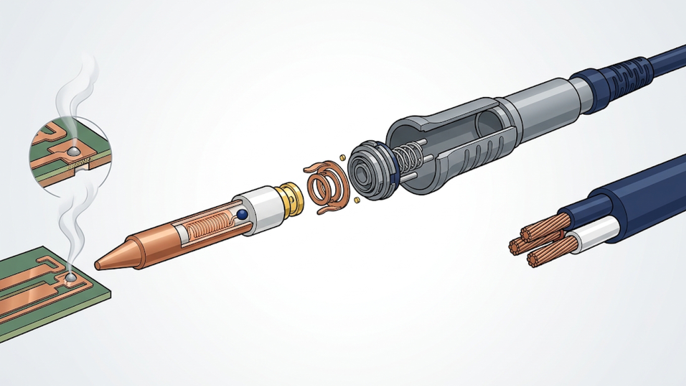
Figure 2. A C210-style handpiece keeps the cartridge, heater-and-sensor region, contacts, and handle body aligned so the controller can regulate the working end.
How Does a C210 Cartridge Heat and Sense Temperature?
The heater is a resistive load. When the controller applies an appropriate voltage, current flows and electrical energy becomes heat. The simplified relationship is `P = V x I`, and for an ideal constant resistance, `P = V^2 / R`. Real cartridge resistance changes with temperature, while the supply, cable, contacts, switching device, and firmware limit what reaches the heater. Do not infer a universal wattage from one seller's nominal voltage.The sensor is physically near the working end, which helps the controller react to changes at the cartridge. The controller still sees a measurement signal rather than a perfect joint temperature. Sensor offset, reference temperature, ADC conversion, contact resistance, and thermal gradients can all create a difference between the displayed value and the solder joint.
JBC's Most Efficient Soldering System reference explains the manufacturer's approach to fast heating, sleep, and hibernation behavior. Treat those claims as JBC system evidence, not as a benchmark for every C210-compatible product. A third-party controller may use different sampling, control tuning, sleep logic, and calibration constants.
The control cycle normally looks like this:
- Read the selected setpoint and operating mode.
- Enter a measurement condition that keeps switching noise from corrupting the sensor reading.
- Convert the cartridge signal into a temperature estimate.
- Compare the estimate with the setpoint and apply the controller's control law.
- Switch heater power within the supply and safety limits.
- Repeat while checking for an open sensor, impossible reading, overtemperature, supply fault, or idle state.
Which C210 Soldering Tip Shape Should You Choose?
Tip shape controls access, contact area, solder volume, and heat transfer. Start with the joint geometry, not the smallest-looking tip. A tip that cannot make stable contact often transfers less heat than a slightly wider tip that reaches the joint cleanly.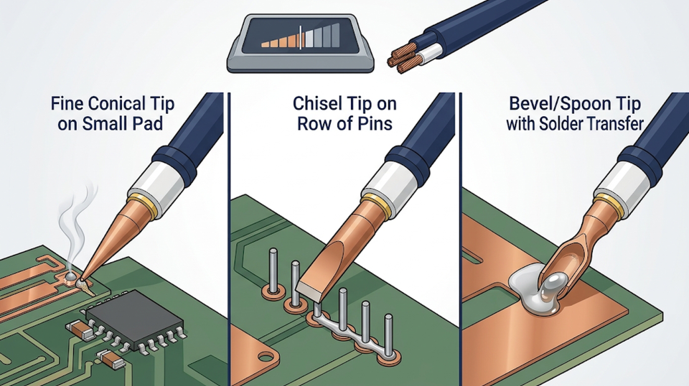
Figure 3. C210 tip geometry should match the joint: fine conical access for small pads, chisel contact for pin rows, and bevel or spoon transfer for broader joints.
| C210 tip shape | Best starting use | Main advantage | Common mistake |
|---|---|---|---|
| Fine conical | Small pads, wire ends, and microscope access | Reaches a tight area with minimal obstruction | Using the very point for every joint, which reduces contact area |
| Conical bent | Angled access around a component or shield | Improves visibility and approach angle | Choosing an angle that touches the neighboring component first |
| Chisel | Pin rows, tabs, and ordinary through-hole joints | Flat face transfers heat across a wider contact patch | Selecting a width that bridges adjacent pins |
| Bevel | Drag soldering, connector pins, and controlled solder loading | Holds a small solder film along an edge | Carrying too much solder into fine-pitch gaps |
| Spoon or barrel | Larger pads and repeatable solder pickup | Holds more solder and can spread heat | Using it where the joint cannot tolerate the extra mass |
| Specialized | Coating removal or unusual production geometry | Matches a defined process fixture | Treating a specialty shape as a general-purpose tip |
JBC's official range lists these shape families and individual C210 part numbers. QUICKO or another supplier may use similar shape names with different dimensions, plating, or cartridge contacts. Record the working width, access angle, and process purpose when ordering. “C210 compatible” does not tell you whether the tip is conical, bent, chisel, bevel, or a specialty design.
What Is the Difference Between C210, C245, and T12?
C210, C245, and T12 are not interchangeable labels. They generally identify different cartridge or heater ecosystems, with different handle contacts, physical dimensions, power behavior, and controller expectations. A station can advertise more than one family, but that is a property of that station and its manual, not a guarantee across the market.| Family | Typical work profile | Relative physical intent | What buyers must verify |
|---|---|---|---|
| C210 | Precision SMD, microscope rework, connectors, and medium-power joints | Small cartridge and precision handle family | T210 or compatible handle, sensor contacts, controller profile, tip dimensions |
| C245 | Higher-power general electronics and larger thermal loads | Larger cartridge family than C210 in many systems | Handle, controller channel, supported power range, tip family, and ground path |
| T12 | Integrated tip, heater, and sensor cartridge ecosystem | Different cartridge geometry and contact arrangement | T12 handle/controller compatibility, supply, pinout, and calibration |
JBC's cartridge catalog and handle pages provide one manufacturer's compatibility map. QUICKO's own product catalog contains T12 products and C210/245 products, but the site pages should be read as separate product entries. For a broader overview of temperature-controlled stations, see QUICKO's temperature-controlled soldering station guide. The guide explains closed-loop control and recovery; this article narrows that system logic to the smaller C210 work profile.
How Do You Verify C210 Compatibility?
Use a written checklist before plugging in a cartridge. A successful fit in the handpiece proves only that the metal body can enter the sleeve; it does not prove that the heater, sensor, ground, and controller paths agree.Compatibility checklist
- Cartridge identity: Confirm the exact C210 series, part number, dimensions, and tip geometry.
- Handle: Verify the handle is designed for C210 or the exact compatible family, not only that the connector looks similar.
- Contacts and pinout: Compare heater, sensor, and ground contacts with the controller manual.
- Controller profile: Check whether the firmware supports the cartridge sensor type, temperature range, calibration offset, sleep mode, and fault detection.
- Supply: Match the station input, DC voltage, current capability, isolation, and fuse requirements.
- Grounding: Confirm the handle and tip ground path if ESD-sensitive boards or exposed conductors are involved.
- Mechanical retention: Check insertion depth, sleeve fit, strain relief, and the safe hot-removal method.
- Process limits: Confirm the tip shape, solder alloy, flux, component temperature limit, and dwell-time target.
How Do You Set Up and Calibrate a C210 Station?
Setup should be conservative because a small cartridge reaches working temperature quickly and exposes a narrow, hot surface.- Inspect the cold system. Check the enclosure, cable, handpiece sleeve, contacts, stand, and cartridge plating. Do not energize damaged or loose hardware.
- Install the approved cartridge. Insert it with power off and the tip cool. Seat it fully without twisting contacts or forcing a bent cartridge.
- Select a process-based setpoint. Start from the solder alloy, component limits, joint mass, tip shape, and dwell-time goal. A higher display number is not a substitute for poor contact.
- Tin the working surface. Use compatible solder and flux to establish a wettable thermal bridge. Follow the supplier's cleaning method; abrasive files can remove plating.
- Allow stabilization. Watch for sensor errors, large oscillation, or an unexpected fault code before touching a board.
- Check calibration when accuracy matters. Use a suitable tip thermometer and a repeatable contact method. Record the tip shape, setpoint, ambient conditions, measurement spread, and any offset applied.
- Test recovery separately. Use a defined copper load and record the minimum temperature and time to return within a chosen band. An unloaded reading cannot prove loaded performance.
How Do You Diagnose Common C210 Faults?
Disconnect power and let the cartridge cool before opening a handpiece or controller. Internal mains-side troubleshooting belongs to a qualified person using suitable isolation and measurement practices.| Symptom | Likely area | First safe checks | Avoid |
|---|---|---|---|
| Display works but cartridge stays cold | Heater path, contacts, supply, or switch | Reseat a cool approved cartridge; inspect contacts; confirm supply rating | Bridging the power switch or powering the heater directly |
| Sensor error or unstable temperature | Sensor contact, cable, polarity, or controller profile | Try one known-compatible cartridge; inspect unpowered contacts; check the manual | Copying a different C210-style pinout |
| Tip heats but fine joints remain cold | Tip geometry, oxidation, copper mass, or low recovery | Tin the tip; use a suitable chisel or bevel; test on a defined load | Raising setpoint repeatedly without fixing contact |
| Overshoot or glowing cartridge | Missing feedback, wrong profile, or failed switch | Turn power off; verify cartridge and controller compatibility | Continuing to heat an uncontrolled tip |
| Station resets during a joint | Supply collapse, cable fault, or protection limit | Check supply behavior under load and connector strain relief | Installing a larger fuse to hide the fault |
| Sleep or stand mode does not work | Handle sensor, stand, or firmware setting | Confirm sensor type, menu mode, and stand alignment | Assuming every C210 handle has the same motion sensor |
Change one variable at a time. A known-good cartridge, a verified handle, and a documented supply can isolate many problems, but swapping all three at once makes the result hard to interpret. Record the symptom, setpoint, tip part number, load, and controller message before replacing parts.
What Should Buyers Compare Before Ordering?
Compare the complete C210 work system rather than the tip name alone.- Precision access: Does the handle let you see the joint under a microscope, and does the catalog include the conical, bent, chisel, bevel, or specialty geometry you need?
- Recovery evidence: Is there a repeatable load test with a defined tip, setpoint, copper mass, minimum temperature, and recovery threshold?
- Compatibility evidence: Are the approved cartridges, handle, controller, pinout, sensor type, voltage, and ground path documented together?
- Calibration and safety: Can you set an offset, verify the reading, configure sleep, and identify sensor or overtemperature faults?
- Serviceability: Are replacement cartridges, sleeves, cables, stands, and manuals available from a stable source?
- Process fit: Will the station handle your board's copper area and solder alloy without forcing you to overheat delicate components?
Frequently Asked Questions
Is a C210 soldering iron the same as a T210 handle?
No. C210 usually identifies a cartridge family, while T210 identifies a compatible precision handle family in JBC's system. A complete setup still needs a controller, power stage, cable, and safe stand. Third-party products may use similar names with different contacts or calibration, so check the exact documentation before combining parts.What is a C210 soldering tip used for?
C210 tips are commonly used for precision joints, SMD work, microscope rework, connectors, and conventional components where access and controlled contact area matter. Choose the shape from the joint: conical for access, chisel for pin rows, bevel for solder loading, and spoon or barrel for broader heat transfer.Can I use a C210 cartridge in a C245 soldering station?
Not automatically. C210 and C245 generally represent different cartridge and handle ecosystems. A station may support both only when its manual specifies the correct handle, contacts, firmware profile, and power limits. Mechanical insertion or a shared product photo is not proof of electrical or temperature compatibility.Is a C210 soldering iron suitable for large ground planes?
It can work for some medium joints when the tip geometry, supply, and controller provide enough recovery, but the small precision format is not a universal answer for high thermal loads. Test with the actual copper area and record minimum temperature and recovery time before using it in production.How do I know whether a C210 temperature display is accurate?
Use a suitable tip thermometer with a repeatable contact method after stabilization. Record setpoint, tip part number, ambient conditions, measurement spread, and any offset. Then test under load. Agreement at idle does not prove that the joint stays within process limits when copper, pins, or a ground plane remove heat.Conclusion
A C210 soldering iron is best understood as a precision cartridge system: a small working tip, heater, sensor, handpiece, controller, and power path that must agree. Its advantages are access, controllable contact area, and a compact thermal path for fine electronics work. Its limits appear when a mismatched handle, unverified pinout, weak supply, worn plating, or undersized tip is asked to handle a larger thermal load.Before ordering, choose the tip shape from the joint, verify the cartridge and handle as a pair, confirm the controller and supply, and run a repeatable loaded recovery check. That process gives QUICKO buyers a safer basis for comparing C210 options than a maximum temperature number alone.
Publication Safety Note
Soldering creates burn, fire, electrical, molten-metal, and fume hazards. Use eye protection, a stable stand, ventilation or appropriate fume control, heat-resistant handling tools, and the solder and flux safety data supplied for the process. Wash hands after handling lead-containing materials. Disconnect power before servicing, and do not open mains-powered equipment unless you are qualified to work safely on it.Sources and Evidence Boundaries
- JBC Soldering, C210 Cartridge Range, accessed August 18, 2026. Used for C210 use cases, cartridge shape families, and compatible handle references; manufacturer claims remain bounded as manufacturer evidence.
- JBC Soldering, T210 handles, accessed August 18, 2026. Used for handle-and-cartridge compatibility context.
- JBC Soldering, Most Efficient Soldering System, accessed August 18, 2026. Used for the manufacturer's heating, sleep, and hibernation architecture claims.
- JBC Shop, C210 Cartridge Guide PDF, accessed August 18, 2026. Used as a catalog reference for cartridge families and part-number organization.


Linkedin:


